Improvements in and relating to remote sensing

a remote sensing and light technology, applied in the field of remote sensing systems and methods, can solve the problems of difficult environment limited use of raman lidar methods, and limited use of raman techniques, so as to improve the amount of light, improve the effect of staying, and reduce aberrations in images formed

Active Publication Date: 2018-12-13
BAE SYSTEMS PLC
View PDF0 Cites 7 Cited by
  • Summary
  • Abstract
  • Description
  • Claims
  • Application Information

AI Technical Summary

Benefits of technology

[0009]In this way, the system is able to take account of the distorting effect of the optical path traversed by returned light emanating from an illuminated optical element, as the light travels to the detector, and to estimate that distorting effect by determining the shape of the distorted wavefront of the returned light. If an optical element is sufficiently distant or sufficiently small (or both), then the light emanating from it would tend to reach the detector with substantially parallel, un-distorted wavefronts in the absence of any distorting effects along the optical path between the optical element and the detector. Thus, it is possible to reliably conclude that any wavefront distortion present within the received wavefront is the result of such distorting effects.
[0010]The inventor has realised that it is possible to use this information not simply to improve the wavefront of the returned light, which has the effect of reducing aberrations in images formed using that light, but instead to at least partially counteract the distorting effects imposed on output illumination light as it travels along the optical path between the optical element and the detector in the opposite direction—i.e. from the illuminator to the remote optical element. The inventor has been surprised to find that this has the effect of significantly improving the amount of light that is subsequently returned by the optical element (e.g. by a factor of ×5 or ×10 in some implementations). It is believed that by anticipating and at least to some extent counteracting the expected distortions that will be applied to the wavefront of outgoing illumination light, it is possible to permit the illumination light to reach a target optical element with a less distorted wavefront which the optical element is able to interact with more effectively. Put another way, the optical element may ‘see’ the illumination light to be more spatially stable and scintillating less. Consequently, the illumination light may be better at staying ‘on target’ by the time it reaches the optical element. Preferably, the reflector unit is arranged to deform...

Problems solved by technology

This makes the Raman technique more difficult to utilise in environments where transmission windows are restricted (e.g. underwater).
Consequently, Raman techniques are limited in their use.
Remote sensing techniques such as Brillouin and Raman lidar methods tend to be limited by the very low levels o...

Method used


Image

  • Improvements in and relating to remote sensing
  • Improvements in and relating to remote sensing
  • Improvements in and relating to remote sensing

Examples


Embodiment Construction

[0059]In the drawings, like items are assigned like reference symbols.

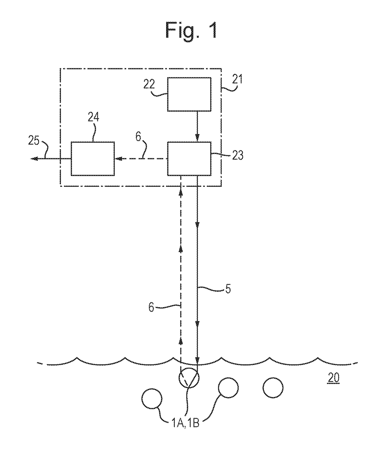
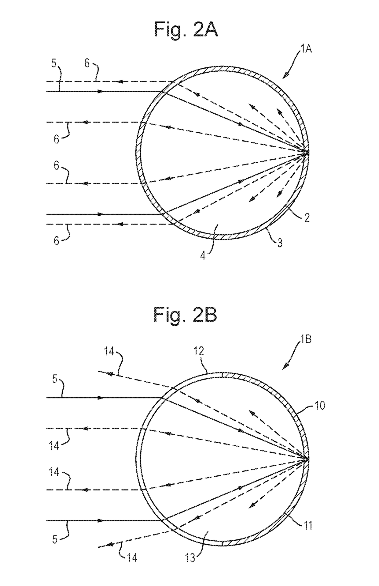
[0060]FIG. 1 schematically illustrates a system for remotely sensing light 6 emanating from within a monitored environment 20 (e.g. the open sea in this case). The system includes a plurality of retro-reflective optical elements (See FIGS. 2A and 2B: items 1A, 1B) comprising photo-luminescent coated glass beads structured in accordance with a bead as described below with reference to either one of FIGS. 2A and 2B. The optical elements are positioned within the monitored environment 20 and float at or beneath the water surface of that environment. Typically, about one bead per cubic metre of volume observed (e.g. ocean water, or the atmosphere in other applications) is suitable, or one bead per metre of height / depth of the space being observed.

[0061]A monitoring unit 21 is located above the water surface of the monitored environment and comprises a laser light source 22 arranged to output a beam of light of wavelen...


PUM


Abstract

A system for remotely sensing light from within a monitored environment containing one or more retro-reflective optical elements. The system includes an illuminator including a light source and a reflector unit comprising a deformable mirror arranged to receive light from the light source and to reflect the received light. This outputs illumination light from the illuminator for illuminating the optical element(s) within the monitored environment. A detector is arranged to receive light returned by the one or more retro-reflective optical elements in response to the illumination light. The detector determines a wavefront of the returned light and detects a property of the monitored environment according to the returned light. The reflector unit is arranged to deform the deformable mirror according to the determined wavefront such that light from the light source is reflected by the deformable mirror so deformed to output illumination light with a modified wavefront.

Description

FIELD OF THE INVENTION[0001]The invention relates to remote sensing systems and methods. In particular, though not exclusively, the invention relates to free-space optical methods of remote sensing.BACKGROUND[0002]Conventional free-space optical remote sensing techniques rely on irradiating a monitored environment with light intended to interact with that environment in a manner which produces a detectable change. In particular, by analysing the light that has been backscattered by target molecules within the monitored environment, such as water molecules, information about the state of those molecules may be gleaned. By inference, one may deduce the state of the environment of which those molecules form a part. For example, spectral shifts in the optical frequency of return optical signals resulting from inelastic optical interactions with a target molecule may be detected. These shifts can be either to a lower frequency (Stokes) or to a higher frequency (Anti-Stokes). By using a p...

Claims


Application Information

Patent Timeline
IPC IPC(8): G01N21/64G01K11/20G01L11/02G02B26/06
CPCG01N21/643G01K11/20G01L11/02G02B26/06G01N2021/1793G01N2201/06193G02B5/126G01N21/6489G01S7/4802G01S7/481G01S7/4811G01S7/497G01S17/74G01S17/95G01N21/63Y02A90/10
Inventor LAYCOCK, LESLIE CHARLES
Owner BAE SYSTEMS PLC
Why Eureka
Try Eureka