Powder chamber for an air-polishing device and air-polishing device

a technology of air-polishing device and air-polishing chamber, which is applied in the direction of manufacturing tools, dental surgery, dental tools, etc., can solve the problems of irregular powder flow, difficult control of small powder flow (100 m), and inability to complete the emptying of the powder chamber all the time, so as to improve the emptying behavior, the effect of constant flow rate and good flow control

Pending Publication Date: 2018-12-20
FERTON HLDG
View PDF0 Cites 0 Cited by
  • Summary
  • Abstract
  • Description
  • Claims
  • Application Information

AI Technical Summary

Benefits of technology

[0005]Therefore, to the disclosure provides a powder chamber for an air-polishing device and an air-polishing device that enables a very constant flow rate, good flow control and which provides an improved emptying-behavior with no or a low residue of powder within the powder chamber.

Problems solved by technology

Nevertheless, the system presents different issues: the powder needs to flow up to a suction nozzle, but it is well known that the flow of small powders (<100 μm) is difficult to control.
Additionally, the complete emptying of the powder chamber is not achieved all the time and the powder flow shows irregularities during emptying of the powder chamber.
Such system may have a varying flow rate and a relatively high residue inside the powder chamber because the powder may get stuck in the chamber due to self-blockade.
Another solution to overcome the problem is to change completely the powder delivery process by using some vibrating system like described in GB 2 347 372 A. Such systems are complicated and have also problems using very fine powders.

Method used


Image

  • Powder chamber for an air-polishing device and air-polishing device
  • Powder chamber for an air-polishing device and air-polishing device
  • Powder chamber for an air-polishing device and air-polishing device

Examples


Embodiment Construction

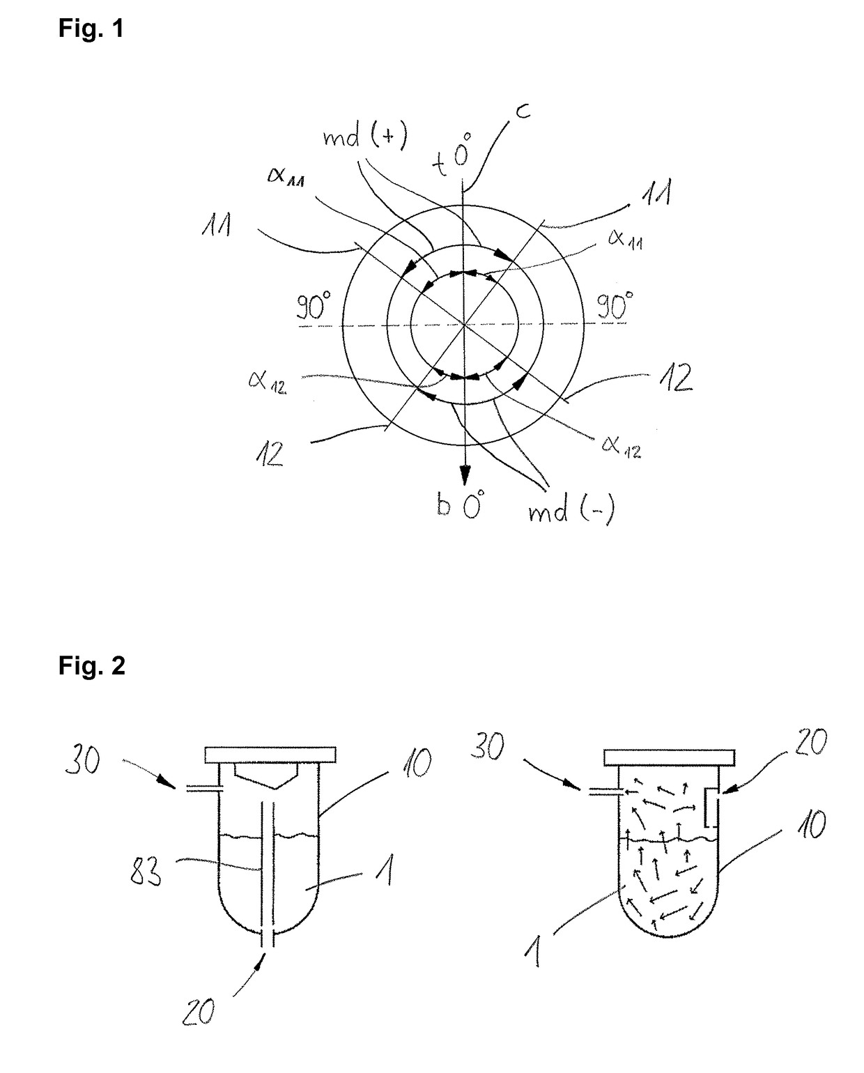
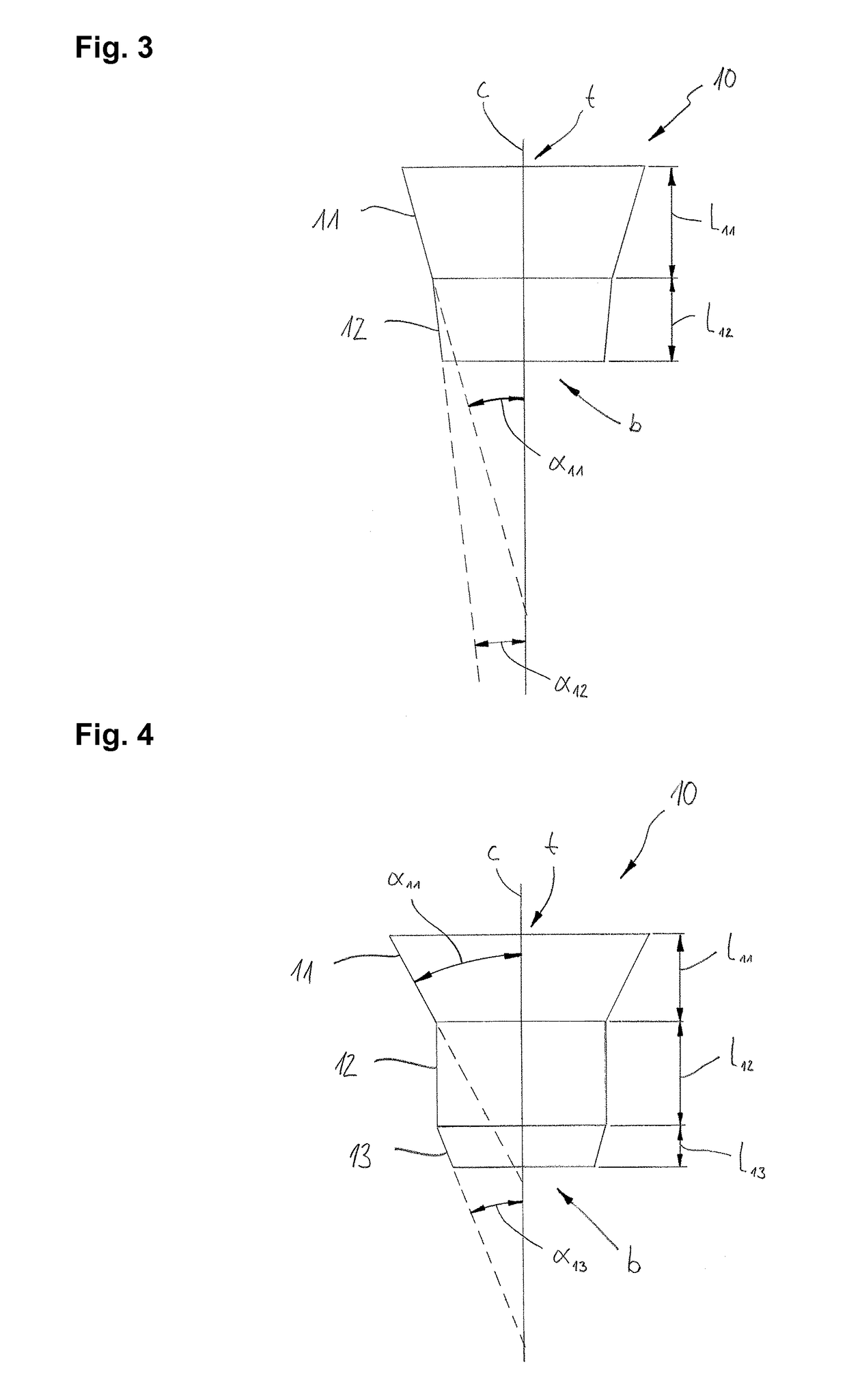
[0049]FIG. 1 shows the measuring scheme used to define the angles. An axis c is shown that extends from a top end t to a bottom end b of a powder chamber (not shown). A first wall section 11 and a second wall section 12 extend along the axis c. The wall sections are only used by way of example to explain a measuring direction md. First angles all are measured from the axis c to the wall section 11, so that the acute angle is obtained. The same applies to second angles α12 that are formed between the second wall section 12 and the axis c. If the measuring direction is directed from the top end t to the bottom end b, the angles are counted positive. If the measuring direction md is directed from the bottom end b to the top end t, the angles are counted negative. Positive angles reach from 0° to −90°.

[0050]FIG. 2 shows two working principles of air-polishing devices, in particular of powder chambers 10. The powder chambers 10 are filled, for example, with powder 1, such as sodium bicar...


PUM


Abstract

Powder chamber for an air polishing device, extending from a top end to a bottom end along an axis, said powder chamber including at least two wall sections, where a first wall section forms a first angle with respect to the axis, and wherein a second wall section forms a second angle with respect to the axis, wherein the angles are measured in a measuring direction from the axis to the appropriate wall section in such a manner so that the acute angles are obtained, wherein the measuring direction) from the top end to the bottom end is counted positive, and wherein the measuring direction from the bottom end to the top end is counted negative, wherein the second wall section is arranged below the first wall section, and wherein the second angle is smaller than the first angle.

Description

TECHNICAL FIELD[0001]This invention relates to a powder chamber for an air-polishing device and to an air-polishing device.BACKGROUND[0002]Air-polishing devices, in particular air-polishing devices that comprise powder chambers, are used in the sand blasting technology, e.g. in the dental field. In this technology a powder is used for the dental prophylaxis, wherein the powder is a low abrasive powder, as for example sodium bicarbonate, calcium carbonate, glycine or erythritol. To avoid damaging of the teeth, the powder has a small grain size ranging from about 100 μm down to about 13μm on average. There are mainly two ways to take out the powder from the powder chamber: one is by injecting air from the top of the powder chamber and the other is by injecting the air from the bottom of the powder chamber.[0003]The second method delivers the most accurate powder flow rate and enables the best treatment. Nevertheless, the system presents different issues: the powder needs to flow up to...

Claims


Application Information

Patent Timeline
Patent Type & Authority Applications(United States)
IPC IPC(8): A61C3/025B24C7/00
CPCA61C3/025B24C7/0053B24C7/0069B24C7/0046B24C11/005
Inventor DONNET, MARCELSAUVAGEOT-MAXIT, KARINE
Owner FERTON HLDG
Why Eureka
Try Eureka