

Rotary wing vtol with fixed wing forward flight mode
a technology of forward flight mode and fixed wing, applied in the field of aircraft, can solve the problems of 25% upper practical limit for forward speed, extreme energy dissipation multiple, lack of adequate net airspeed,
- Summary
- Abstract
- Description
- Claims
- Application Information
AI Technical Summary
Benefits of technology
Problems solved by technology
Method used
Image

Examples
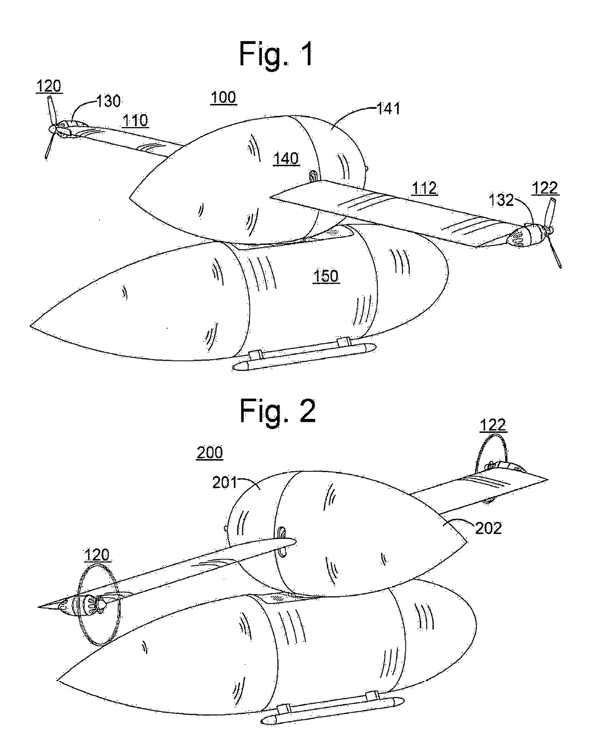
embodiment 100
[0098]These detail illustrations of embodiment 100 show all the powered system components and their powering batteries (FIG. 21: rectangular block 2120 on top of the flapping yoke) and electronics module (FIG. 21: the almost hemispherical nose module 2130) residing in the hub fairing 141. In the event that independent power is available (e.g. from separate batteries) for fuselage components, then the fuselage yaw control motor could be flipped and moved into the fuselage, with appropriate bearing adjustments (for example to have the large spur gear coupled to the bottom of the cylindrical flapping yoke extension emerging from the middles of the bearings, rather than to the bearing sleeve.) Further components for radio communication, flight control computations, picture taking, etc., are readily moved down into the fuselage, with wireless communication (e.g. RF or infrared LED-Photodiode pairs) conveying control information up into the hub and / or down from hub and wing sensors into t...
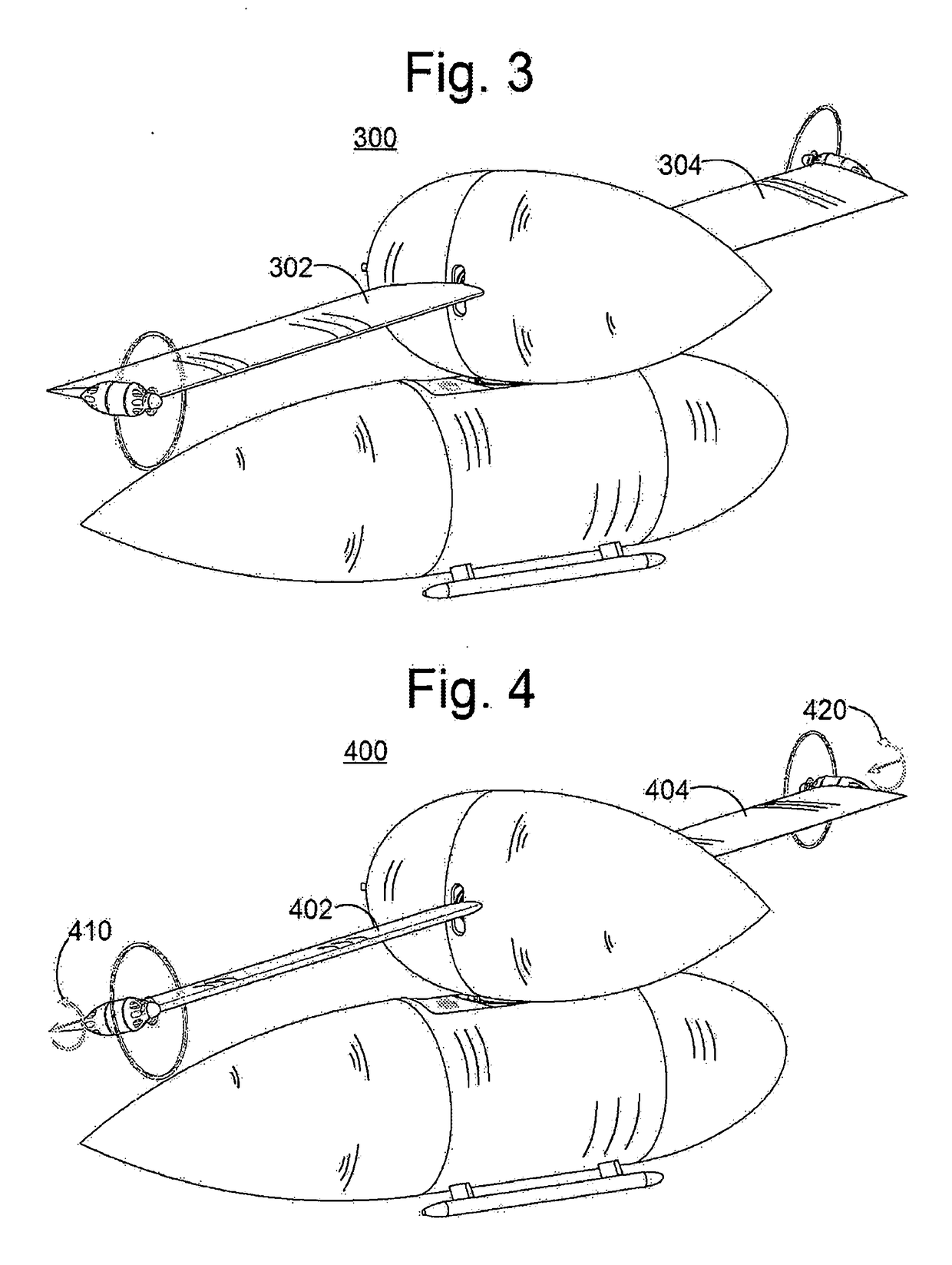
embodiment 3000
[0212]The pitch control system of 3100 certainly requires such compensations. In the discussion of embodiment 3000 and its diagram, pressure sensor apertures 3050, 3054, 3058, 3051, 3055 and 3059 were discussed in relation to lift coefficient computations from pressure signals. Indeed, the kind of computation taking place in computation subsystem 3270 is very general and can use inputs 3261 and 3262 from a variety of types of pitch sensors, including the pressure sensor system just mentioned. As indicated in FIG. 32b, lift coefficients for input to 3270 can be derived indirectly from other signals that will be available to an aircraft control system. The list of symbols at 3275 indicates some of the types of system measurements that may optionally be used in combination to infer wing lift coefficients. Here the Greek “LP” is taken to represent Yaw angle, while the dot above the second instance of the symbol indicates the time derivative, i.e. the Yaw rate-of-change. Here also the Gr...
PUM
 Abstract
Description
Claims
Application Information