Power tool

a technology of power tools and fusing terminals, applied in the field of power tools, can solve the problems of time-consuming effort and cost, difficult to deal with the increase in the number of coils, and limit the layout of the respective fusing terminals, and achieve the effect of merely dealing with even a complex coil connection structur

Inactive Publication Date: 2019-01-03
MAKITA CORP
View PDF17 Cites 8 Cited by
  • Summary
  • Abstract
  • Description
  • Claims
  • Application Information

AI Technical Summary

Benefits of technology

[0027]The power tool including a motor according to the present invention is capable of simply dealing with even a complex coil connection structure.

Problems solved by technology

Therefore, limitations are imposed on the layout of the respective fusing terminals 42, and it is difficult to deal with increase in number of the coils 23 and so forth.
This requires time-consuming effort and cost.

Method used


Image

  • Power tool
  • Power tool
  • Power tool

Examples


Embodiment Construction

[0041]An embodiment and modifications of the present invention will be hereinafter explained based on drawings on an as-needed basis.

[0042]In the embodiment and modifications, directional terms “front”, “rear”, “up”, “down”, “right” and “left” are defined for convenience of explanation, and are changed in accordance with a work condition, a state of a member in movement, and so forth.

[0043]It should be noted that the present invention is not limited to the following embodiment and modifications.

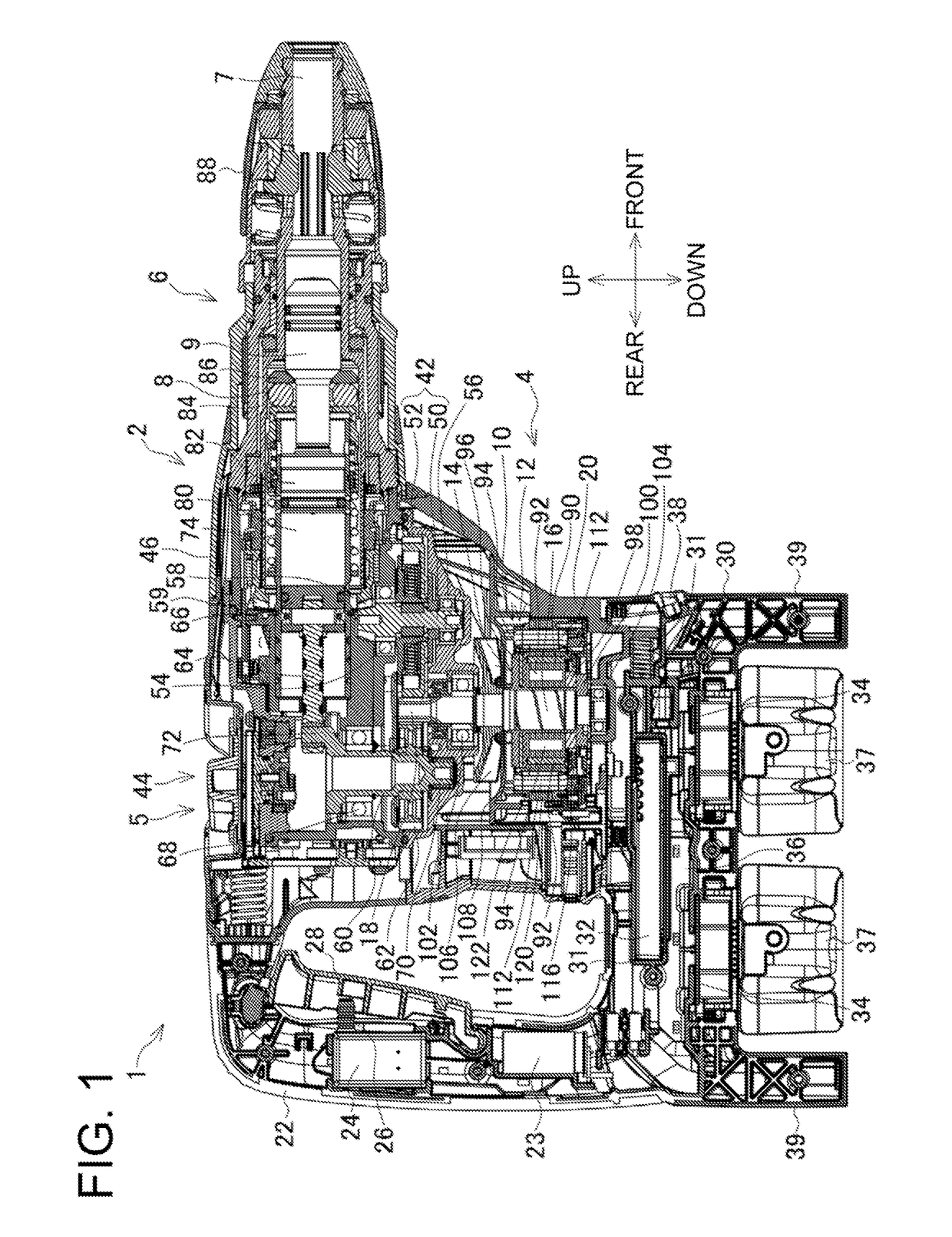
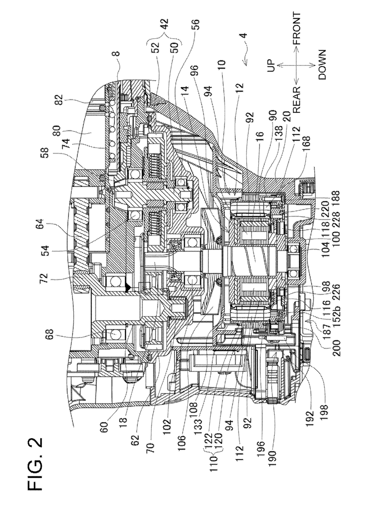
[0044]FIG. 1 is a vertical, central, cross-sectional view of a hammer drill 1 as an example of a power tool (impact tool) according to the embodiment, whereas FIG. 2 is an enlarged view of a front part in FIG. 1.

[0045]The hammer drill 1 includes a housing 2, a power part 4, an intermediate part 5 and an output part 6. The housing 2 is a frame for holding a variety of members. The power part 4 is disposed in the middle of the housing 2, and generates a power. The intermediate part 5 is dispose...


PUM


Abstract

It is intended to provide a power tool including a motor capable of simply dealing with even a complex coil connection structure.
A hammer drill includes a plurality of coils, a stator holding the plurality of coils, a rotor that is rotatable with respect to the stator, and a terminal unit including a plurality of fusing terminals electrically connected to the plurality of coils.

Description

CROSS-REFERENCE TO RELATED APPLICATIONS[0001]This application claims the benefit of priority to Japanese Patent Application No. 2017-130585, filed on Jul. 3, 2017, the entire contents of which are hereby incorporated by reference.BACKGROUND1. Technical Field[0002]The present invention relates to a power tool such as a hammer drill.2. Description of the Background[0003]A type of hammer drill including a brushless motor has been known as described in Japan Laid-open Patent Application Publication No. 2015-56953 (hereinafter referred to as “Patent Literature 1”).[0004]A brushless motor 17 described in Patent Literature 1 includes a sensor circuit board (sensor board) 24 and a short circuit member 25. The sensor board 24 is equipped with a rotation detection element. The rotation detection element detects the position of a permanent magnet 63 disposed on a rotor 19, and outputs a rotation detection signal. The short circuit member 25 has a ring shape and includes six short circuit tabs ...

Claims


Application Information

Patent Timeline
Patent Type & Authority Applications(United States)
IPC IPC(8): B23Q5/10H02K7/14H02K3/50H02K3/28H02K3/38H02K15/00
CPCB23Q5/10H02K7/145H02K3/50H02K3/28H02K3/38H02K15/0075H02K2203/03H02K2203/09B23Q2717/00B25D17/00H02K1/165H02K1/2706H02K5/04H02K7/06H02K9/06H02K11/0094H02K3/522B25D2250/095B25D2250/121B25D2250/145B25D2250/221B25F5/00H02K15/0068
Inventor NAGAHAMA, TATSUYA
Owner MAKITA CORP
Why Eureka
Try Eureka