Improved electro-thermal heating

a technology of electro-thermal heating and electro-thermal heating, which is applied in the direction of wind turbines, mechanical equipment, machines/engines, etc., can solve the problems of reducing the speed of wind turbine rotation, affecting the efficiency of wind turbines, and affecting the operation of wind turbines in cold climates

Pending Publication Date: 2019-01-03
VESTAS WIND SYST AS
View PDF11 Cites 9 Cited by
  • Summary
  • Abstract
  • Description
  • Claims
  • Application Information

AI Technical Summary

Benefits of technology

[0020]The icing factor may indicate a severity of an icing event. As the

Problems solved by technology

Wind turbines situated in cold climates can suffer from icing events where ice may be formed on the surface of the wind turbine blades due to freezing water on the cold surface.
The accumulation of ice on the surface of a blade can result in undesirable consequences.
For example, a change in the profile of the wind turbine blades due to the accumulation of ice may reduce the speed of rotation of the wind turbine.
As a result, the wind turbine may operat

Method used


Image

  • Improved electro-thermal heating
  • Improved electro-thermal heating
  • Improved electro-thermal heating

Examples


Embodiment Construction

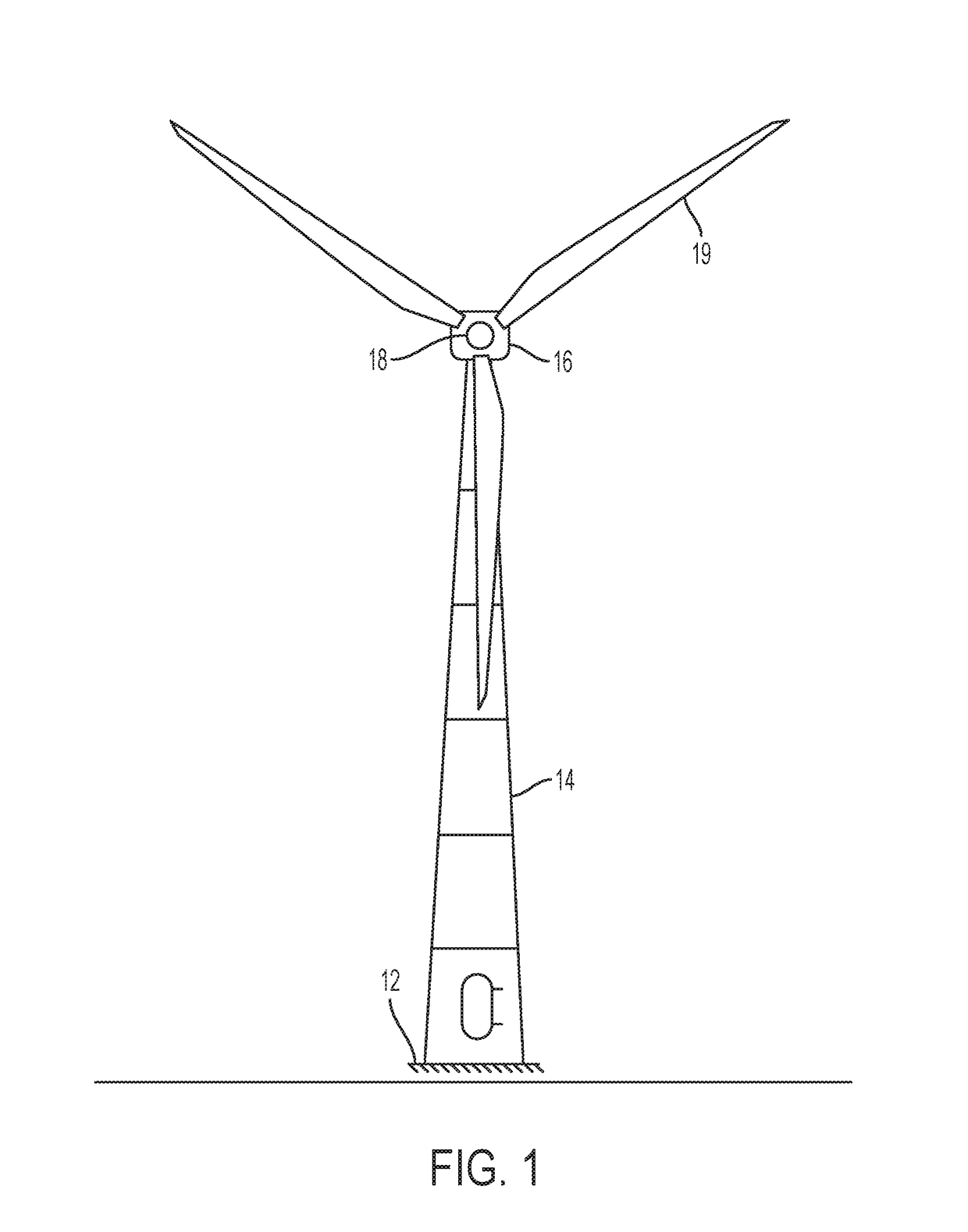
[0040]FIG. 1 shows a schematic of a typical wind turbine 10 which includes embodiments of wind turbine blades 20 according to the present invention. The wind turbine 10 is mounted on a base 12 which may be onshore foundations or off-shore platforms or foundations. The wind turbine includes a tower 14 having a number of tower sections. A nacelle 16 is located and attached to the top of tower 14. A wind turbine rotor, connected to the nacelle 16, includes a hub 18 and at least one wind turbine blade 20, where in FIG. 1 three wind turbine blades are shown although any number of wind turbine blades 20 may be present depending on the design and implementation of the wind turbine 10. The wind turbine blades 20 are connected to the hub 18 which in turn is connected to the nacelle 16 through a low speed shaft which extends out of the front of the nacelle 16.

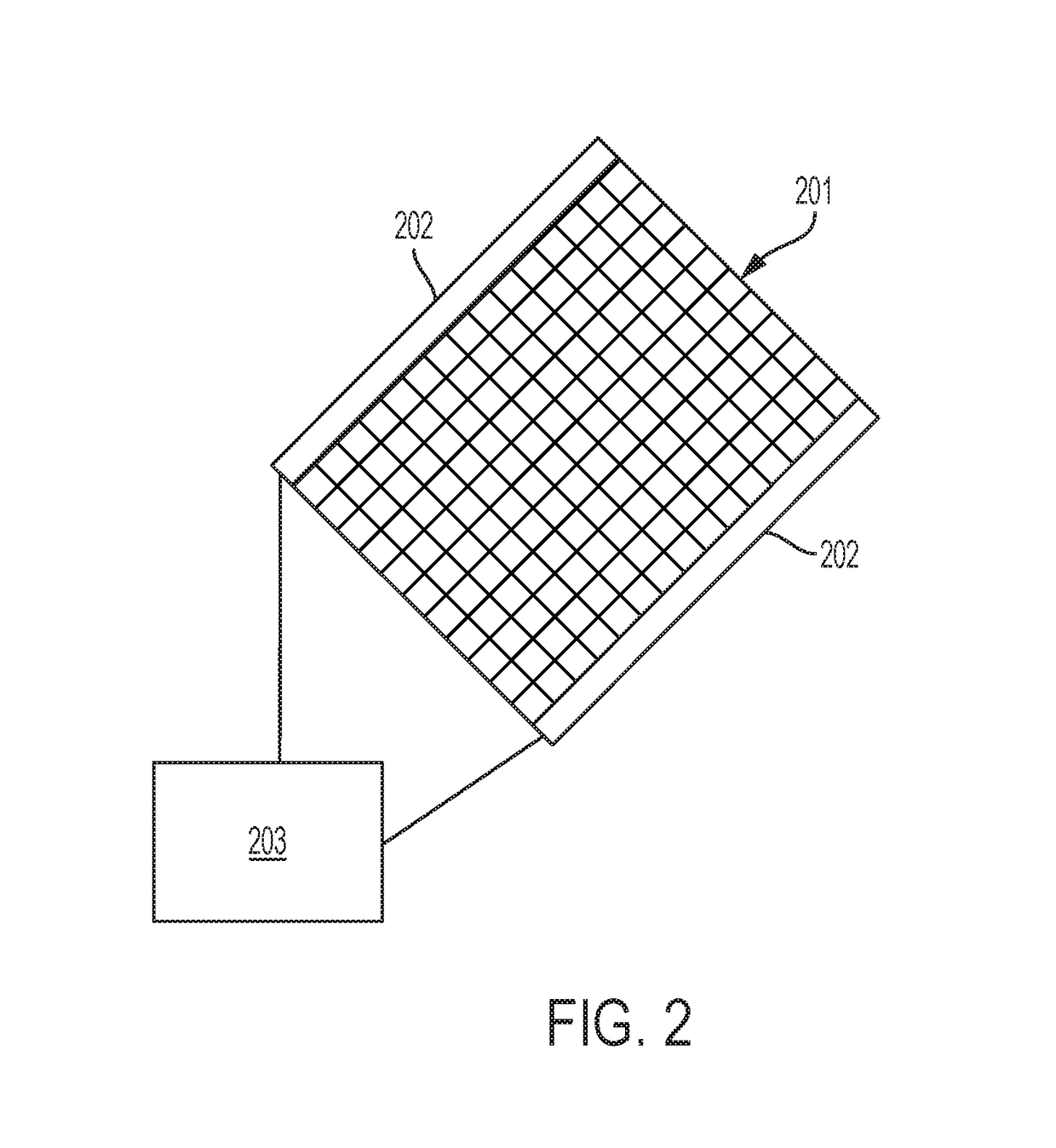
[0041]FIG. 2 shows a schematic of an Electro-Thermal Heating (ETH) element 201 which may be embedded within a wind turbine blade struct...


PUM


Abstract

The present invention relates to a method and controller for heating a wind turbine blade that comprises a plurality of heating zones. An icing factor is determined based on environmental conditions and one or more heating zones are determined based on the determined icing factor, wherein each heating zone comprises one or more Electro-Thermal Heating Elements. The one or more Electro-Thermal Heating Elements corresponding to the determined heating zones are activated to generate heat.

Description

[0001]The present invention relates to Electro-Thermal Heating (ETH) and in particular to an improved control of ETH for Wind Turbine Blades.[0002]Wind turbines generate electrical power from wind energy and can be situated on land or off-shore. Wind turbines situated in cold climates can suffer from icing events where ice may be formed on the surface of the wind turbine blades due to freezing water on the cold surface. The accumulation of ice on the surface of a blade can result in undesirable consequences. For example, a change in the profile of the wind turbine blades due to the accumulation of ice may reduce the speed of rotation of the wind turbine. As a result, the wind turbine may operate below optimal speed and efficiency which degrades the performance of the wind turbine. Also, the additional weight of the accumulating ice on the wind turbine blades may cause fatigue and stress failures of the blades.[0003]Therefore, there is a need to be able to prevent or reduce the effec...

Claims


Application Information

Patent Timeline
IPC IPC(8): F03D80/40F03D17/00
CPCF03D80/40F03D17/00F05B2270/325F05B2270/323F05B2270/32F05B2270/309Y02E10/72
Inventor BUGGY, STEPHENSPANDLEY, LUKEBADGER, PAUL
Owner VESTAS WIND SYST AS
Why Eureka
Try Eureka