Fourier transform infrared spectrophotometer
a technology of infrared spectrophotometer and transform, which is applied in the direction of interferometric spectrometry, optical radiation measurement, instruments, etc., can solve the problem of phase difference between two beams of infrared light and each other, and achieve the effect of efficient us
- Summary
- Abstract
- Description
- Claims
- Application Information
AI Technical Summary
Benefits of technology
Problems solved by technology
Method used
Image
Examples
first embodiment
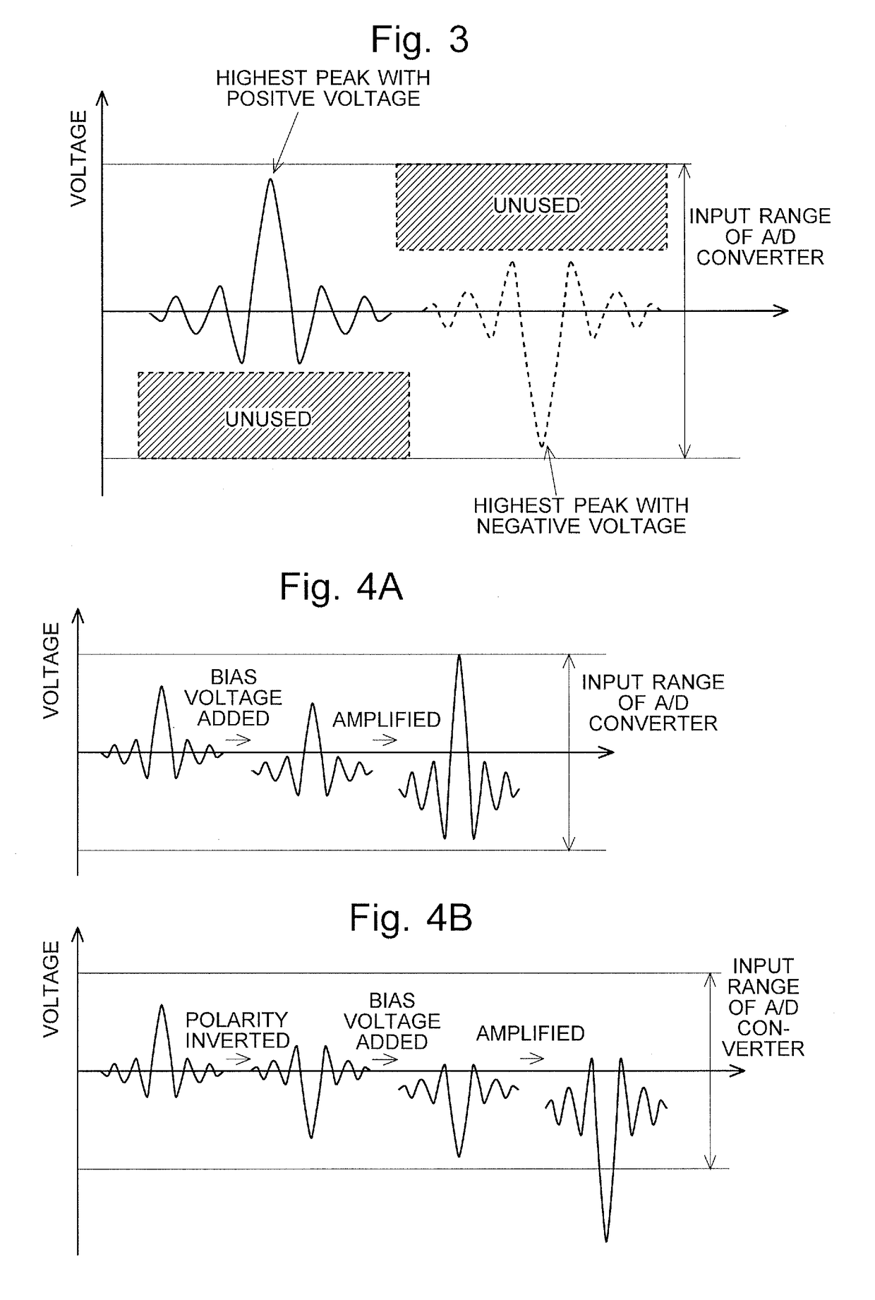
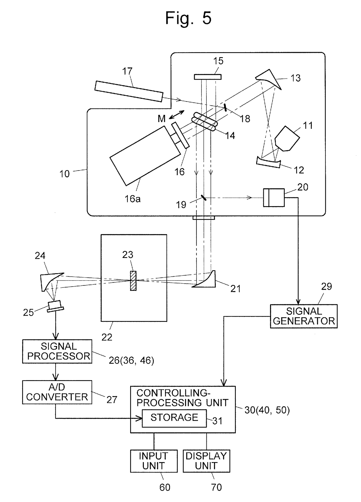
[0071]FIG. 6 shows the configuration of the signal processor 26 and the controlling-processing unit 30 used in the Fourier transform infrared spectrophotometer according to the first embodiment. The signal processor 26 in the first embodiment includes: a polarity inverter 261 for outputting a voltage obtained by inverting the polarity of an input voltage; a bias voltage adder 262 for adding a bias voltage with a predetermined magnitude to an input voltage; and an amplifier 263 for amplifying an input voltage by a predetermined multiplying factor. The polarity inverter 261, bias voltage adder 262 and amplifier 263 each actually consist of electric circuits, in which the function of each component (which will be described later) is realized by an appropriate combination of various kinds of conventionally known electric circuits. The controlling-processing unit 30 includes a judging section 32 and a signal-processing determining section 33 as its functional blocks in addition to the st...
second embodiment
[0079]FIG. 8 shows the configuration of the signal processor 36 and the controlling-processing unit 40 used in the Fourier transform infrared spectrophotometer according to the second embodiment. The signal processor 36 in the second embodiment includes: a bias voltage adder 362 for adding either a positive bias voltage or negative bias voltage to an input voltage, the two bias voltages having the same absolute value; and an amplifier 363 for amplifying an input voltage by a predetermined multiplying factor. The bias voltage adder 362 and amplifier 363 each actually consist of electric circuits, in which the function of each component (which will be described later) is realized by an appropriate combination of various kinds of conventionally known electric circuits. Similar to the controlling-processing unit 30 in the first embodiment, the controlling-processing unit 40 includes a judging section 42 and a signal-processing determining section 43 as its functional blocks in addition ...
third embodiment
[0087]FIG. 10 shows the configuration of the signal processor 46 and the controlling-processing unit 50 used in the Fourier transform infrared spectrophotometer according to the third embodiment. The signal processor 46 in the third embodiment includes: a high-pass filter (HPF) 464 for allowing the passage of only such frequency components of an input voltage signal that are equal to or higher than a predetermined frequency; and an amplifier 463 for amplifying an input voltage by a predetermined multiplying factor. The high-pass filter 464 and amplifier 463 each actually consist of electric circuits, in which the function of each component (which will be described later) is realized by an appropriate combination of various kinds of conventionally known electric circuits. As with the controlling-processing unit 30 in the first embodiment or the controlling-processing unit 40 in the second embodiment, the controlling-processing unit 50 has a storage section 31. However, this unit has ...
PUM
 Abstract
Description
Claims
Application Information
 - R&D
- Intellectual Property
- Life Sciences
- Materials
- Tech Scout
- Unparalleled Data Quality
- Higher Quality Content
- 60% Fewer Hallucinations
Browse by: Latest US Patents, China's latest patents, Technical Efficacy Thesaurus, Application Domain, Technology Topic, Popular Technical Reports.
© 2025 PatSnap. All rights reserved.Legal|Privacy policy|Modern Slavery Act Transparency Statement|Sitemap|About US| Contact US: help@patsnap.com


