Vehicle control system

a technology of vehicle control and control system, which is applied in the direction of battery/fuel cell control arrangement, anti-theft devices, lock applications, etc., can solve the problems of reducing user convenience in some cases, remote control of the vehicle is disabled, etc., and achieves the effect of reducing user convenience, reducing power consumption, and improving user convenien

Active Publication Date: 2019-01-17
HONDA MOTOR CO LTD
View PDF0 Cites 1 Cited by
  • Summary
  • Abstract
  • Description
  • Claims
  • Application Information

AI Technical Summary

Benefits of technology

[0017]According to (1) or (11), the cycle of operation of the receiver is set to the second cycle longer than the first cycle. Hence, power consumption can be suppressed without decreasing user convenience.
[0018]According to (2), if the receiver receives a signal when the cycle of operation of the receiver is set to the second cycle, electric power can be supplied to the specific equipment. Hence, the user can check the operation of the specific equipment, and user convenience can be improved.
[0019]According to (3), if the receiver receives a signal when the cycle of operation of the receiver is set to the second cycle, the cycle of receiving signals is reduced. Hence, signal reception sensitivity can be automatically enhanced.
[0020]According to (4), when a state where no signal is received continues for a predetermined time or longer, the cycle of operation of the receiver is set to the second cycle. Hence, the user can suppress power consumption without any special operation.
[0021]According to (5) or (11), the cycle of intermittent transmission of request signals to the outside of the vehicle is set to the fourth cycle longer than the third cycle. Hence, power consumption can be suppressed without decreasing user convenience.
[0022]According to (6), the cycle of transmission of request signals is extended, and the cycle of intermittent reception of signals is also extended. Hence, power consumption can be suppressed even more.

Problems solved by technology

However, since the above system stops operation of the reception circuit of the Smart Entry control means completely, remote control of the vehicle is disabled.
This decreases user convenience in some cases.

Method used


Image

  • Vehicle control system
  • Vehicle control system
  • Vehicle control system

Examples


first embodiment

[Configuration]

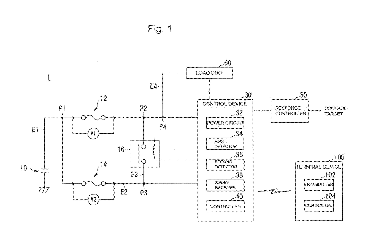
[0039]FIG. 1 is a diagram illustrating one example of a functional configuration of a vehicle control system 1 installed in a vehicle. For example, the vehicle control system 1 includes a first voltage detector V1, a second voltage detector V2, a battery 10, a first fuse 12, a second fuse 14, a relay circuit 16, a control device 30, a response controller 50, a load unit (specific equipment) 60, and a mobile terminal 100. The vehicle control system 1 also has a first feed line E1, a second feed line E2, a third feed line E3, and a fourth feed line E4.

[0040]The battery 10, the first fuse 12, the first voltage detector V1, and the control device 30 are connected to the first feed line E1. The second fuse 14, the second voltage detector V2, and the control device 30 are connected to the second feed line E2. The relay circuit 16 is connected to the third feed line E3. The load unit 60 is connected to the fourth feed line E4.

[0041]In the first feed line E1, one end of the b...

application example

[0074]Hereinafter, an exemplar application of the vehicle control system 1 of the embodiment will be described. For example, assume a case where several tens or several hundreds of vehicles are displayed at a car dealer. In such a case, in a vehicle control system of a comparative example, a fuse between a battery and a load unit may be disconnected to keep electric power of the battery from being supplied to the load unit and lowering SOC. When the fuse is disconnected, the battery and the load unit are brought out of conduction. Hence, decrease in SOC can be suppressed. However, in order for the salesperson to demonstrate functions (e.g., operational states of meters, audio, car navigation and the like) of the load unit (specific equipment) of the vehicle to the customer, the fuse needs to be connected to bring the battery and the load unit into conduction. Thus, it has been difficult in some cases to achieve both suppression of decrease in SOC and improvement in user convenience ...

second embodiment

[0079]Hereinafter, a second embodiment will be described. In the second embodiment, when a first fuse 12 is disconnected, a control device 30A that transmits a request signal to a mobile terminal 100A sets a longer transmission cycle of a request signal than when the first fuse 12 is connected. Hereinbelow, points different from the first embodiment will mainly be described.

[0080]FIG. 9 is a diagram illustrating a functional configuration of the control device 30A and the mobile terminal 100A of a vehicle control system 1A of the second embodiment. The control device 30A further includes a signal transmitter 39. The signal transmitter 39 transmits a request signal that requests transmission of identification information to the mobile terminal 100A.

[0081]Upon receipt of a response signal, which is a response to the request signal, from the mobile terminal 100A after transmission of the request signal by the signal transmitter 39, a controller 40 performs communication processing betw...


PUM


Abstract

A system includes; a first power line connectable with a first fuse and feeds electric power from a battery to a controller; a second power line connectable with a second fuse and feeds electric power from the battery to the controller; a first detector that detects whether the first fuse is connected; a second detector that detects whether the second fuse is connected; and the controller that causes specific equipment to operate upon detection of receipt of a signal by a receiver that operates intermittently to receive signals from a mobile terminal. The controller sets a cycle of operation of the receiver to a first cycle when the first fuse is connected, and set the cycle of operation of the receiver to a second cycle longer than the first cycle, when it is detected that the first fuse is not connected, and the second fuse is connected.

Description

CROSS-REFERENCE OF RELATED APPLICATION[0001]This application claims priority of Japanese Patent Application No. 2017-136890 filed in Japan on Jul. 13, 2017, the entire contents of which are incorporated herein by reference.TECHNICAL FIELD[0002]The present invention relates to a vehicle control system.BACKGROUND OF THE INVENTION[0003]Conventionally, a system has been disclosed (see Japanese Patent Application Publication No. 2015-93634, for example) in which periodic start control of a reception circuit of Smart Entry control means by a battery is stopped, on condition that a control circuit detects disconnection of a backup fuse that electrically interrupts a feed line from the battery to a general load. With the control described above, the system can restrict an unnecessary dark current in the reception circuit of the Smart Entry control means by completely stopping operation of the reception circuit, even when the vehicle is unused for a long period of time. Thus, the system prev...

Claims


Application Information

Patent Timeline
Patent Type & Authority Applications(United States)
IPC IPC(8): B60L11/18B60R16/03
CPCB60L11/1851B60L2240/54B60L11/1816B60R16/03B60R25/403B60R25/406E05B49/00B60L2240/547B60L2240/549B60L58/14Y02T10/92Y02T10/70B60L58/10
Inventor SATO, MASASHIUEDA, SHINICHIITO, TAKASHIKODA, YUJIROSUDA, SATOSHI
Owner HONDA MOTOR CO LTD
Why Eureka
Try Eureka