Left atrial appendage closure apparatus

a technology for closure of left atrial appendages and valves, which is applied in the direction of prosthesis, surgery, pharmaceutical delivery mechanisms, etc., can solve the problems of bleeding risk, large limitations, and inability to completely close the left atrial valve, and achieve the effect of reducing the damage to the blood vessel

Active Publication Date: 2019-01-24
SHENZHEN KYD BIOMEDICAL TECH CO LTD
View PDF17 Cites 5 Cited by
  • Summary
  • Abstract
  • Description
  • Claims
  • Application Information

AI Technical Summary

Benefits of technology

[0035]The left atrial appendage closure apparatus according to the invention is repositionable. In some cases, if the placement is not good enough, the closure apparatus can be recovered to the sheath tube, and repositioned on the conditions without removing from a pushing rod until the satisfa

Problems solved by technology

Apart from the discomfort brought by the symptom of palpitation, the occurrence of the thromboembolism and other complications are the main hazards of atrial fibrillation.
Among all the methods, the occlusion of left atrial appendage by surgical procedure has not been widely used because of its great trauma and high risk.
At present, the most common means to prevent stroke in patients with atrial fibrillation is receiving long-term oral anticoagulant drugs, but the anticoagulant drugs will induce the bleeding risk and about 14% to 44% of patients fail to receive long-term anticoagulant therapy because of contraindications.
These types of left atrial appendage closure apparatus can all be inserted into the left atrial appendage through catheter intervention to achieve the occlusion effect of the left atrial appendage, but considerable limitations are existing among all of them.
The inner wall of the left atrial appendage is uneven, the shape is irregular and the wall is thin, so it is difficult to realize both the non piercement of the wall and the solid fixation inside the left atrial appendage without falling off, and ultimately achieve the ideal occlusion effect.
But the lower anchorage strength of the braided fixation plate makes it difficult to adapt to the different shapes of the left atrial appendage.
Even if the anchor hook is sutured on the fixation plate, the fixation plate is also difficult to stab into the left atrial appendage wall under the condition of the extrusion deformation to achieve the stable fixation.
Moreover, the shape of the sealing plate will be affected by the extrusion deformation of fixed plate in the left atria

Method used


Image

  • Left atrial appendage closure apparatus
  • Left atrial appendage closure apparatus
  • Left atrial appendage closure apparatus

Examples


embodiment 1

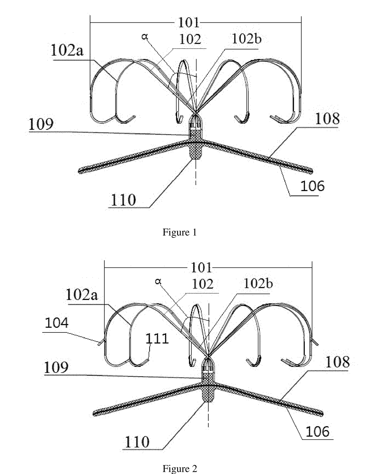
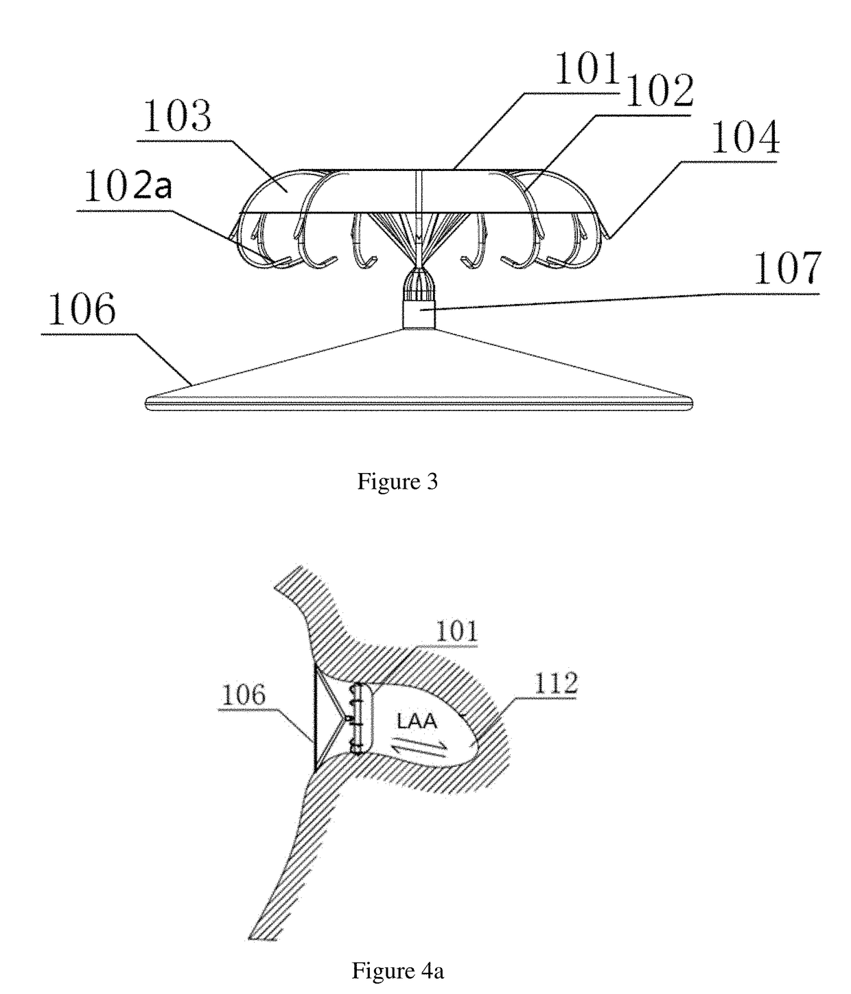
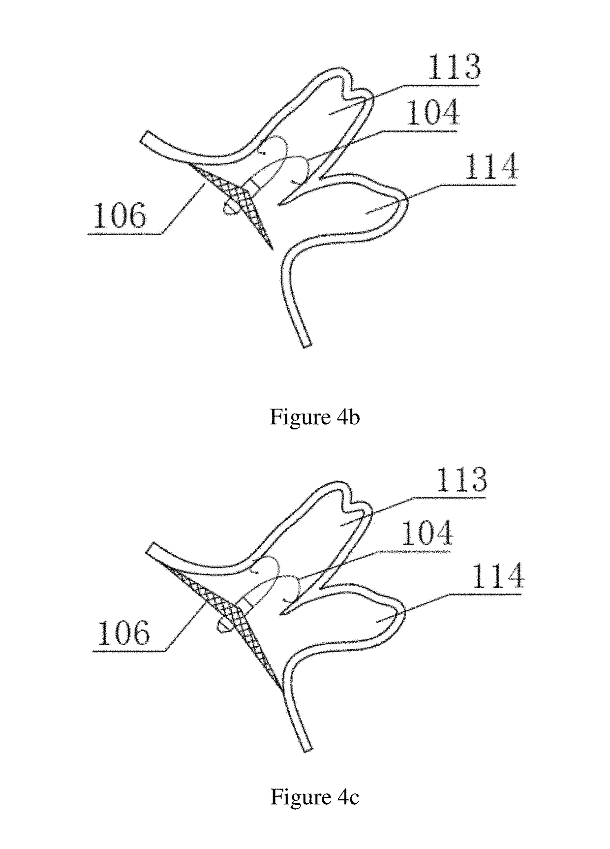
[0052]FIG. 1 described a left atrial appendage closure apparatus, including a sealing plate 106 and an anchor plate 101 connected to the sealing plate.

[0053]The sealing plate was in a mesh structure and arranged with a choke membrane 108 inside, the sealing plate's distal end was fixed by a tubular member 109 and was connected with the anchor plate by the other end of the tubular member which was opposite to the end fixed the sealing plate, the proximal end of the sealing plate was fixed with a fastener 110 and had a structure can connect a convey device.

[0054]The end of the tubular member at the other side away from the end fixed the sealing plate was arranged with a plurality of supporting rods 102, the supporting rods originated from the direction away the sealing plate and the proximal ends 102b of the supporting rods crossed the tubular member center to the opposite side, the supporting rods were intersecting radially arranged to form the anchor plate 101. The angle a between t...

embodiment 2

[0055]A left atrial appendage closure apparatus described in FIG. 1, including a sealing plate 106 and an anchor plate 101 connected to the sealing plate.

[0056]The sealing plate was in a mesh structure and arranged with a choke membrane 108 inside, the sealing plate's distal end was fixed by a tubular member 109 and was connected with the anchor plate by the other end of the tubular member which was opposite to the end fixed the sealing plate, the proximal end of the sealing plate was fixed with a fastener 110 and had a structure which could connect a convey device.

[0057]The end of the tubular member at the other side away from the end fixed the sealing plate was arranged with a plurality of supporting rods 102, the supporting rods originated from the direction away the sealing plate and the proximal ends 102b of the supporting rods crossed the tubular member center to the opposite side, the supporting rods were intersecting radially arranged to form the anchor plate 101. The angle ...

embodiment 3

[0059]A left atrial appendage closure apparatus described in FIG. 2, including a sealing plate 106 and an anchor plate 101 connected to the sealing plate.

[0060]The sealing plate was in a mesh structure and arranged with a choke membrane 108 inside, the sealing plate's distal end was fixed by a tubular member 109 and was connected with the anchor plate by the other end of the tubular member which was opposite to the end fixed the sealing plate, the proximal end of the sealing plate was fixed with a fastener 110 and had a structure which could connect a convey device.

[0061]The end of the tubular member at the other side away from the end fixed the sealing plate was arranged with a plurality of supporting rods 102, the supporting rods originated from the direction away the sealing plate and the proximal ends 102b of the supporting rods crossed the tubular member center to the opposite side, the supporting rods were intersecting radially arranged to form the anchor plate 101. The angle ...


PUM

PropertyMeasurementUnit
Temperatureaaaaaaaaaa
Timeaaaaaaaaaa
Angleaaaaaaaaaa

Abstract

A left atrial appendage closure apparatus for obstructing the left atrial appendage, comprises a sealing plate and an anchored plate. The sealing plate is in a mesh structure and arranged with a choke membrane inside, in addition, the sealing plate adopts a tubular member for the distal fixation and is connected with the anchor plate by the tubular member. The proximal end of the sealing plate is fixed with a fastener provided with a structure connecting a convey device, meanwhile, the end of the tubular member at the other side away from the end fixed the sealing plate is arranged with a plurality of supporting rods, which are intersecting radially arranged to form the anchored plate.

Description

TECHNICAL FIELD[0001]The present invention relates to an implantable medical device and in particular relates to a highly effective, repeatable deployment, stable fixed and fatigue resistant left atrial appendage closure apparatus which enables to closure the left atrial appendage and obstruct the outflow of thrombus in the left atrial appendage.BACKGROUND ART[0002]At present, with the development of the interventional apparatus, many untreatable diseases with surgery have been treated. Compared with surgical treatment, the interventional therapy possesses the advantages of less trauma, faster recovery and better efficacy. During the past half century, the interventional therapy has been developed rapidly, and various kinds of interventional medical devices have also been created to be used for treating more and more diseases and patients.[0003]Atrial fibrillation (AF) is one of the most common arrhythmias. Apart from the discomfort brought by the symptom of palpitation, the occurre...

Claims


Application Information

Patent Timeline
IPC IPC(8): A61B17/12
CPCA61B17/12122A61B17/12031A61B17/12145A61B17/1215A61B2017/00796A61B2017/00831A61B2017/1205A61B17/0057A61B17/12172A61B17/12177A61B2017/00575A61B2017/00579A61B2017/00592A61B2017/00597A61B2017/00615A61B2017/00938A61L31/06A61L31/14A61L2400/18C08L67/02A61B17/12A61F2/00
Inventor CHEN, YILONGHUANG, WEI
Owner SHENZHEN KYD BIOMEDICAL TECH CO LTD
Why Eureka
Try Eureka