Device and system to measure and assess superficial muscle contractile characteristics
a technology of contractile characteristics and devices, applied in the field of biomechanics, can solve the problems of limited muscle testing, limited access to valuable information, and high cost of muscle testing, and achieve the effects of reducing the number of patients, and increasing the difficulty of muscle testing
- Summary
- Abstract
- Description
- Claims
- Application Information
AI Technical Summary
Benefits of technology
Problems solved by technology
Method used
Image
Examples
first embodiment
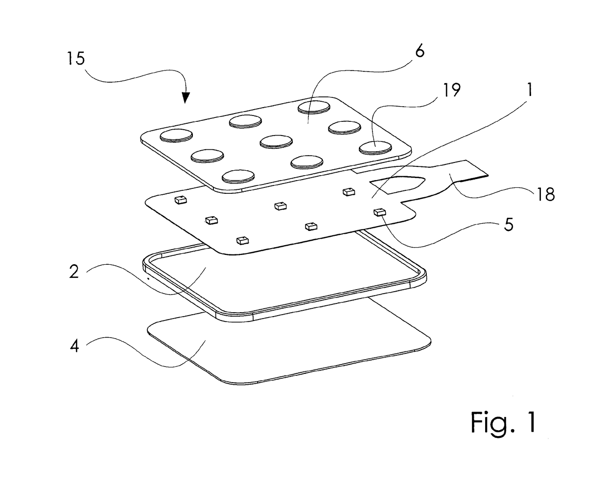
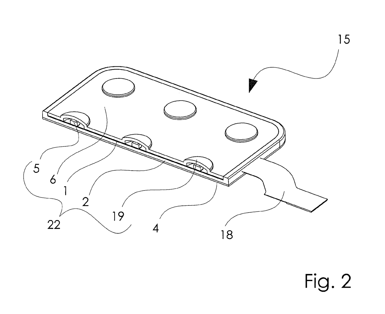
[0029]FIGS. 1 and 2 show a sensor pad assembly 15 of the present invention. The sensor pad assembly 15 comprises nine, three-axis accelerometers 5 connected to a flexible circuit board 1 comprising a tail 18 at one end. The accelerometers 5 and flexible circuit board 1 comprise a sensor array.
[0030]A sensor array assembly 22 comprises: the covering 6; the flexible circuit board 1; the accelerometers 5; and a flexible housing body 2.
[0031]The flexible housing body 2 is shaped to house the flexible circuit board 1. The flexible housing body 2 protects the sensor array assembly 22 from being damaged. A flexible protective covering 6 comprises nine cells 19 such that the accelerometers can rest within the cells 19
[0032]A disposable hydrogel adhesive layer 4 is applied to the underside of the housing body 2 to keep the sensor array assembly 22 in place when used on a person. The adhesive provides a bond with a person's skin. The hydrogel adhesive layer 4 can be disposed of and replaced w...
second embodiment
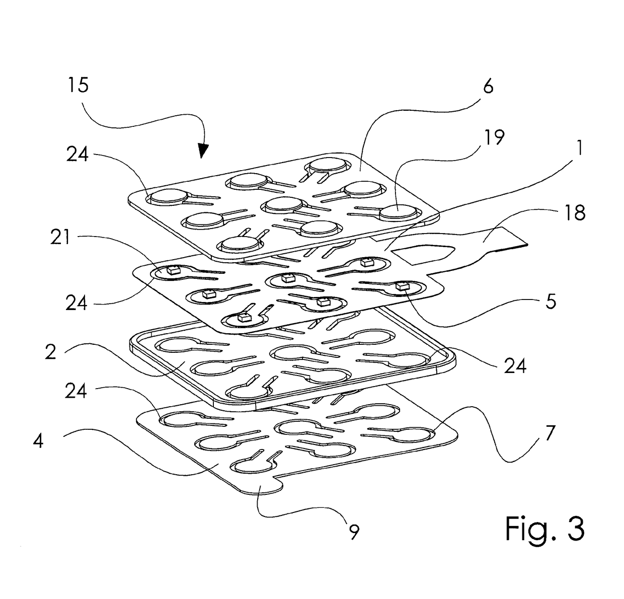
[0034]FIGS. 3 and 4 show a sensor pad assembly 15 of the present invention. The sensor pad assembly 15 comprises nine, three-axis accelerometers 5 connected to a flexible circuit board 1 comprising a tail 18 at one end. The accelerometers 5 and flexible circuit board 1 comprise a sensor array.
[0035]A flexible housing body 2 is shaped to house the flexible circuit board 1. A flexible protective covering 6 comprises nine cells 19 such that the accelerometers can rest within the cells 19.
[0036]A sensor array assembly 22 comprises: the covering 6; the flexible circuit board 1; the accelerometers 5; and the flexible housing body 2.
[0037]A disposable hydrogel adhesive layer 4 is applied to the underside of the housing body 2 to keep the sensor array assembly 22 in place when used on a person. The adhesive provides a bond with a person's skin. The hydrogel adhesive layer 4 can be disposed of and replaced when no longer sufficiently adhering to skin.
[0038]In use, the sensor pad assembly 15 ...
third embodiment
[0041]FIGS. 5 and 6 show a sensor pad assembly 15 of the present invention with means for connecting to a control box (not shown). The sensor pad assembly 15 comprises sixteen, three-axis accelerometers 5 connected to a flexible circuit board 1. The accelerometers 5 and flexible circuit board 1 comprise a sensor array. The flexible circuit board 1 is joined to a connector 16 for an eight conductor cable. There are three chips 17 located on the tail 18 of the flexible circuit board 1. These chips 17 receive data from the accelerometers 5 and convert it to a signal that is relayed to the control box (not shown).
[0042]A flexible housing body 2 shaped to house the flexible circuit board 1 comprises sixteen cells 19 such that the accelerometers can rest within the cells 19. A flexible protective covering 6 formed by pouring a layer of electronic potting material provides a cover over the circuit board 1 to protect the sensor array from being damaged.
[0043]A sensor array assembly 22 compr...
PUM
 Abstract
Description
Claims
Application Information
 - R&D
- Intellectual Property
- Life Sciences
- Materials
- Tech Scout
- Unparalleled Data Quality
- Higher Quality Content
- 60% Fewer Hallucinations
Browse by: Latest US Patents, China's latest patents, Technical Efficacy Thesaurus, Application Domain, Technology Topic, Popular Technical Reports.
© 2025 PatSnap. All rights reserved.Legal|Privacy policy|Modern Slavery Act Transparency Statement|Sitemap|About US| Contact US: help@patsnap.com


