Danger detection in an intended lane change

a technology for detecting dangers and intended changes, applied in the direction of scene recognition, process and machine control, instruments, etc., can solve the problems of sudden force to slam on the brakes, dangerous situations, and underestimated differences in speed between the current used traffic lane and the traffic lane to which a change is intended, and achieve the effect of saving processing tim

Active Publication Date: 2019-01-24
ROBERT BOSCH GMBH
View PDF7 Cites 10 Cited by
  • Summary
  • Abstract
  • Description
  • Claims
  • Application Information

AI Technical Summary

Benefits of technology

[0028]In one further, particularly advantageous embodiment of the present invention, the behavior of other vehicles is assumed to be cooperative to the extent that they are not switching to the traffic lane currently used by the ego vehicle. This is a considerable...

Problems solved by technology

When traveling on superhighways and expressways, errors during a lane change frequently lead to dangerous situations.
Vehicles traveling in the passing lane are suddenly forced to slam on the brakes because of vehicles merging in front of them, or an accident may even happen.
A frequent cause is that the differences in speeds between the currently used traffic lane and the traffic lane to which a change is intended are underestimated.
At speeds of 250 km/h and more, this would necessitate a detection radius of at least 300 m, which is beyond the capabilities of many of the currently employed sensors.
It may then be perceived as annoying if a warning is output despite the fact that it is visually quite obvious to the driver that no other vehicle with which a conflict could arise after the intended lane change is to be found as far as the eyes can see.
On the other hand, poorer visibility might tempt the driver to undertake a possibly dangerous lane change, for instance because the driver perceives only the wall of fog but not the other veh...

Method used


Image

  • Danger detection in an intended lane change
  • Danger detection in an intended lane change
  • Danger detection in an intended lane change

Examples


Embodiment Construction

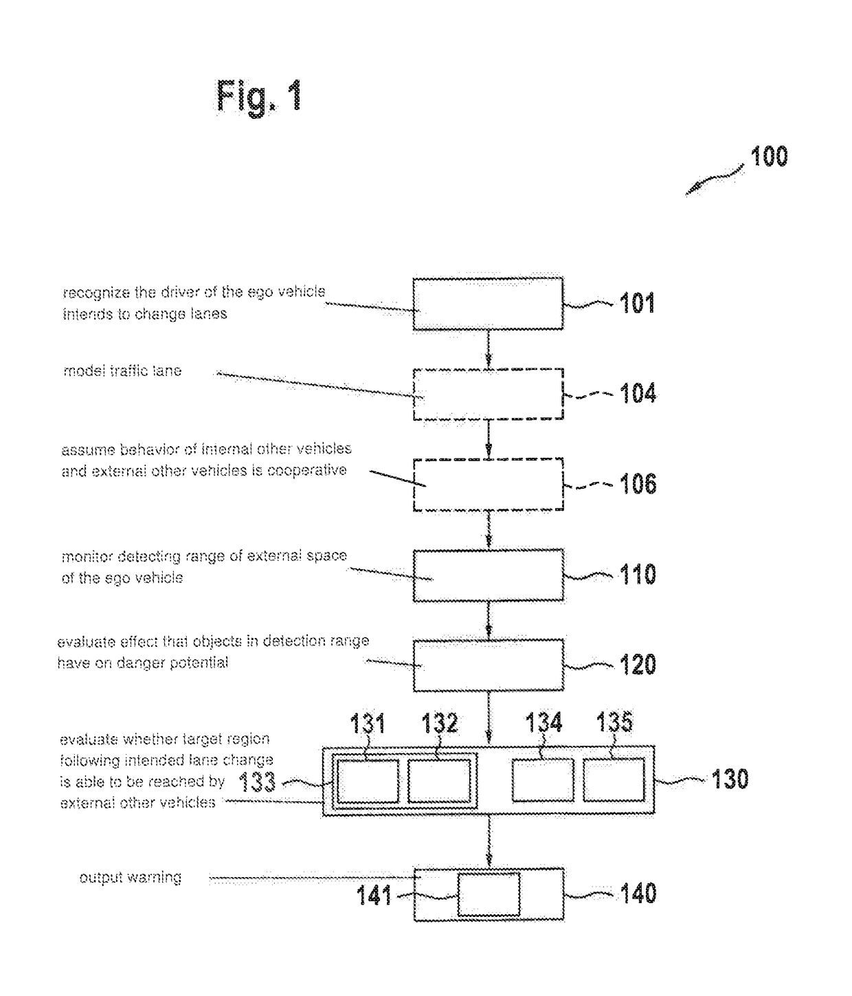
[0036]The exemplary embodiment of method 100 shown in FIG. 1 is used for assisting a human driver, and thus begins in step 101 with the recognition that the driver of ego vehicle 1 intends to change lanes. This step 101 is omitted in the case of an autonomously driving ego vehicle 1 or a vehicle that is driving in an at least partially automated manner.

[0037]Optionally, traffic lane 2a-2c is modeled as a graph 7 in step 104. Also optionally, in step 106 the assumption is made that the behavior of internal other vehicles 4 and external other vehicles 6 is cooperative.

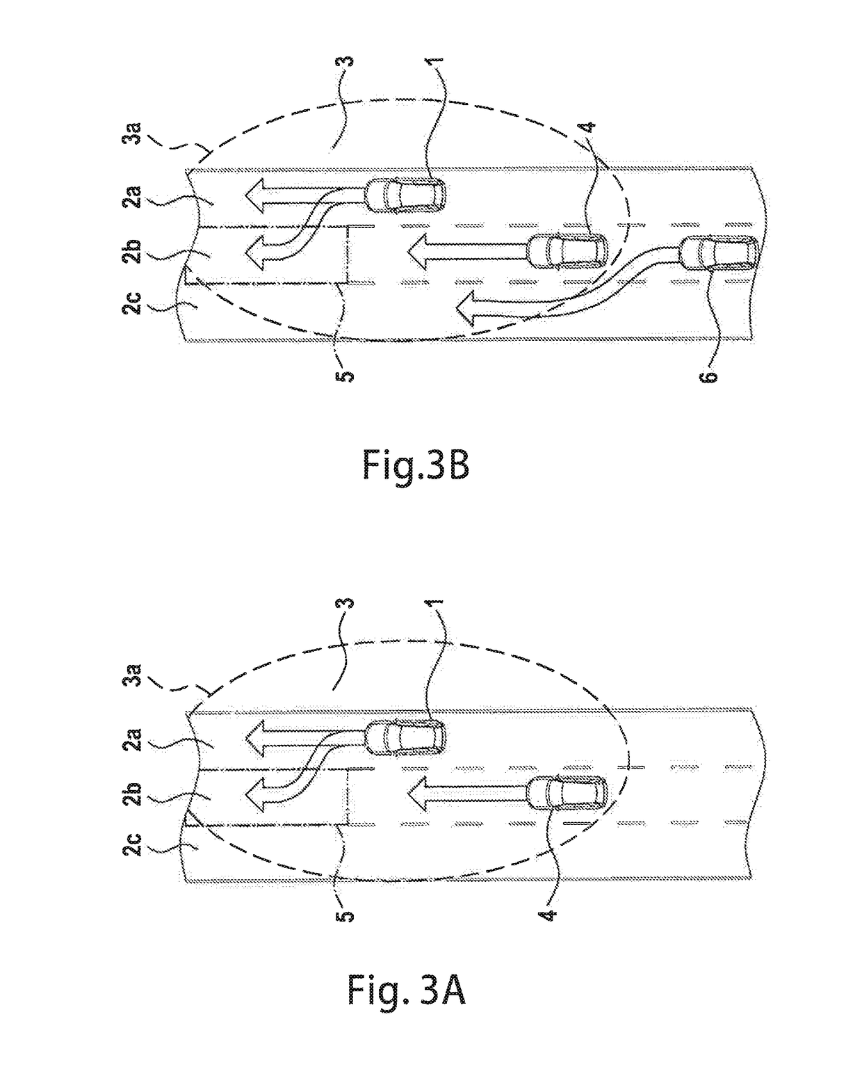
[0038]In step 110, detection range 3 in the external space of ego vehicle 1 is monitored. In step 120, the effect that objects 4 detected in detection range 3 have on the danger potential is evaluated.

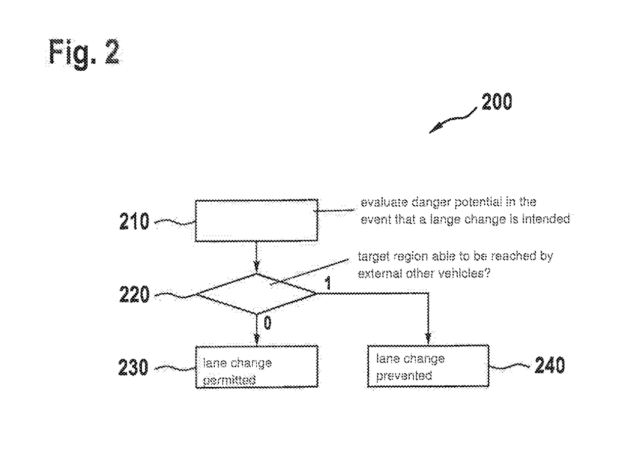
[0039]In step 130, it is then evaluated in accordance with a predefined system of rules, on the basis of positions and speeds of internal other vehicles 4 detected in detection range 3, whether target region 5 in which ego ...


PUM


Abstract

A method for ascertaining the danger potential of a lane change of an ego vehicle from the currently used traffic lane to an adjacent traffic lane, a detection range in the external space of the ego vehicle being monitored, and the effect of objects identified in the detection range on the danger potential is evaluated, and based on positions and speeds of internal other vehicles identified in the detection range, it is determined whether external other vehicles located outside the detection range are able to reach a target region in which the ego vehicle is located following the intended lane change. A method for the at least partially automated control of an ego vehicle, in which in the case of an intended lane change, the danger potential of this lane change is evaluated, and the lane change is prevented if external other vehicles are able to reach the target region.

Description

CROSS REFERENCE[0001]The present application claims the benefit under 35 U.S.C. § 119 of German Patent Application No. DE 102017212277.3 filed on Jul. 18, 2017, which is expressly incorporated herein by reference in its entirety.FIELD[0002]The present invention relates to a method for ascertaining the danger potential of an intended lane change, which method may be used both for assisting human drivers and for at least partially automated driving.BACKGROUND INFORMATION[0003]When traveling on superhighways and expressways, errors during a lane change frequently lead to dangerous situations. Vehicles traveling in the passing lane are suddenly forced to slam on the brakes because of vehicles merging in front of them, or an accident may even happen.[0004]A frequent cause is that the differences in speeds between the currently used traffic lane and the traffic lane to which a change is intended are underestimated. For example, a driver who initiates a passing maneuver of a truck travelin...

Claims


Application Information

Patent Timeline
IPC IPC(8): B60W30/095B60W30/18B60W30/09B60W50/14G05D1/00G06K9/00
CPCB60W30/0956B60W30/0953B60W30/18163B60W30/09B60W50/14G05D1/0088G06K9/00805G06K9/00825G05D2201/0213B60W2050/143B60W30/08B60W40/04B60W40/10G08G1/166G08G1/167B60W2554/80B60W30/095B60W30/10B60W2540/20B60W2554/00G06V20/58G06V20/584B60W2540/18B60W2554/4041
Inventor PINK, OLIVERSCHWINDT, OLIVER F.
Owner ROBERT BOSCH GMBH
Why Eureka
Try Eureka