Distributed Optical Fibre Sensors

Active Publication Date: 2019-01-24
VIAVI SOLUTIONS INC
View PDF0 Cites 32 Cited by
  • Summary
  • Abstract
  • Description
  • Claims
  • Application Information

AI Technical Summary

Benefits of technology

[0014]In both of the cases described above, it is advantageous to connect the cluster of sensing fibres to more than one interrogator unit, where the different interrogator units may offer different features, such as tolerance to strong reflections or high attenuation. The invention described herein therefore proposes use of an N:M optical switch between the interrogators and the sensing optical fibres in order to achieve the desired connections flexibly and reconfigurably under programmable and therefore automatic control.
[0015]When an N:M optical matrix switch is used as suggested above, then in the case of a fault or breakdown of one interrogator, an alternative working unit can be used to provide sensing capability, for ex

Problems solved by technology

Thirdly, the sensing system typically includes a signal processor that automatically converts the electrical signals into information about the environmental effects, such as vibrations, temperature or static pressure, acting on the sensing optical fibre.
Both the optical interrogator and the signal processor are typically costly elements of the system, while the sensing optical fibre tends to be susceptible to damage and degradation during the lifetime of the system, but is frequently very inaccessible and therefore difficult or impossible to repair or replace.
Another limitation of the prior art architectures of distributed optical fibre vib

Method used


Image

  • Distributed Optical Fibre Sensors
  • Distributed Optical Fibre Sensors
  • Distributed Optical Fibre Sensors

Examples


Embodiment Construction

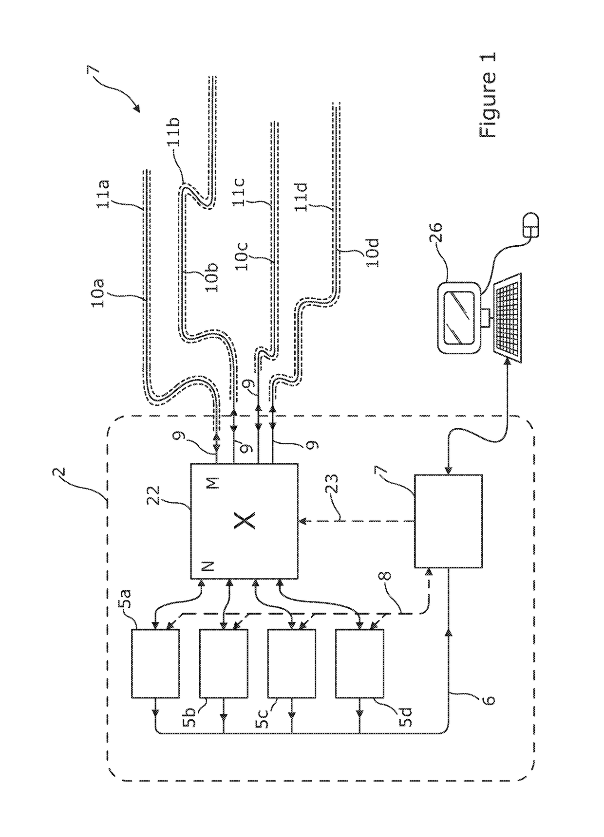
[0043]Referring to FIG. 1 there is illustrated a distributed optical fibre sensor 2 arranged to sense one or more physical parameters of an environment 7 as a function of position along part or all of each of a plurality of sensing optical fibres 10a-10d, using optical time domain reflectometry (OTDR), or another reflectometry technique such as frequency domain reflectometry. The sensing optical fibres may be deemed part of the sensor 2. The sensor comprises a plurality of interrogator units 5a-5d which are optically coupled to the plurality of sensing optical fibres 10a-10d via an optical switch 22 which is preferably arranged to selectively couple any one of the interrogators to any one of the sensing optical fibres. In this way, probe light pulses from any one of the interrogators are directed into a correspondingly coupled sensing optical fibre, and backscattered probe light from that sensing optical fibre is directed back to the coupled interrogator, to thereby effect the sensi...


PUM


Abstract

The disclosure relates to a distributed optical fibre sensor having an optical switch arranged to selectively and simultaneously couple each of a plurality of interrogators to each of a plurality of sensing optical fibres.

Description

[0001]The present invention relates to sensors using multiple optical fibres. Aspects of the invention relate in particular to distributed optical fibre sensors in which one or more physical parameters are sensed as a function of position along a plurality of sensing optical fibres from properties of probe light backscattered within the sensing fibres. Such sensors may for example be optical time domain reflectometry (OTDR) sensors for use in sensing acoustic vibration or other physical parameters, and such sensors which use phase sensitive OTDR techniques such as through the detection of coherent Rayleigh noise, or other interferometric techniques.INTRODUCTION[0002]Distributed optical fibre sensing is a well known approach to providing information about environmental conditions proximal or adjacent to a sensing optical fibre, and avoids the need to use point sensor structures at particular locations such as sensor structures coupled to the optical fibre, or Bragg gratings written i...

Claims


Application Information

Patent Timeline
IPC IPC(8): G01D5/353G01K11/32G01B11/16G01H9/00
CPCG01D5/35361G01K11/32G01D5/35383G01B11/16G01H9/004G01D5/35358G01D5/35396
Inventor STEEL, ADRIANHANDEREK, VINCENT
Owner VIAVI SOLUTIONS INC
Why Eureka
Try Eureka