Method for modifying the dimensions of a cast iron pump part

Active Publication Date: 2019-01-31
FLUID HANDLING
View PDF0 Cites 0 Cited by
  • Summary
  • Abstract
  • Description
  • Claims
  • Application Information

AI Technical Summary

Benefits of technology

The present invention provides new methods to modify cast iron components using additive manufacturing. These methods can improve the efficiency of hydraulic pumps or create difficult-to-cast geometries while avoiding the issue of cracking. The invention allows for the successful deposition of metal structures on cast iron components without potential cracking. These methods involve carefully selecting deposition patterns to control cooling rates and utilizing specific additive manufacture powders in a mixed ratio or layer configuration.

Problems solved by technology

However, limitations offered by conventional manufacturing methods often lead to constraints in design flexibility and pump inefficiencies.
However, deposition of metals on cast iron could be challenging due to the potential for cracking due to thermal effects, built internal stresses, metallurgical discontinuities, chemistry and other.
The redistribution of carbon and microstructural changes taking place during molten metal deposition in turn result in cracking.
Manufacturing techniques for some common pump components often present constrains for incorporating geometrical features and limit component size availability to match specific operation requirements of the pump.
This in turn, could affect pump efficiency and / or limit the number of pump operation range offerings for customers.
Pump companies will often extend the operation range of the pumps by trimming impellers but this affects the pump efficiency in most cases.
However, deposition of metals on some cast iron parts could be challenging due to the potential for cracking due to thermal effects, built internal stresses, metallurgical discontinuities, chemistry and other.

Method used


Image

  • Method for modifying the dimensions of a cast iron pump part
  • Method for modifying the dimensions of a cast iron pump part

Examples


Embodiment Construction

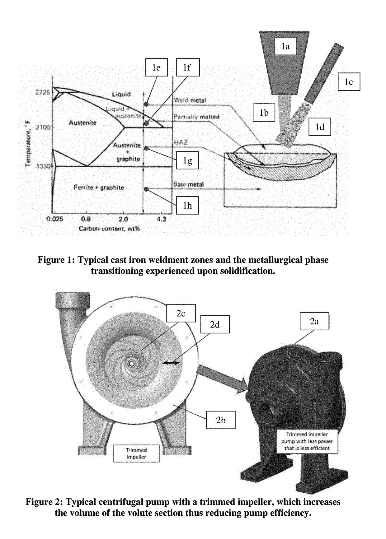
[0041]Deposition of metal on cast iron by thermal means, such as the case with directed energy deposition, has similar challenges of those encountered by hard-to-weld metals. Some types of cast irons, such as gray iron typically used for pump casing manufacturing, are difficult to weld because of its high carbon content, the complex metallurgical phases formed, and the stresses generated during solidification and cooling. FIG. 1 illustrates the metallurgical phase changes undergone by cast iron upon solidification from a molten state during a directed energy deposition process (FIG. 1 is adapted from ASM Specialty Handbook: Cast Irons, Joseph R. Davis, p. 217). Sub-portions labelled 1a through 1d of FIG. 1 illustrate or identify one of several forms of a directed energy deposition known as a laser metal deposition. Sub-portion 1a shows or identifies the laser beam shielding nozzle. Sub-portion 1b shows or identifies the laser beam. Sub-portion 1c shows or identifies the powder feed ...


PUM

PropertyMeasurementUnit
Temperatureaaaaaaaaaa
Fractionaaaaaaaaaa

Abstract

A method for modifying a dimension of a cast iron pump part features placing a cast iron pump part on a base plate of a directed energy deposition (DED) machine; selecting a metal deposition procedure for depositing a metal having a combination of one or more Nickel Alloys or Nickel powders on the cast iron pump part; and depositing the metal on the cast iron pump part to modify the dimension of the cast iron pump part, based upon the metal deposition procedure selected. The selecting of the metal deposition procedure includes forming the metal by mixing metal powders that include a Nickel Alloy “A” in a specified mixed ratio with a pure Nickel powder “B” for depositing on the cast iron pump part.

Description

CROSS-REFERENCE TO RELATED APPLICATION[0001]This application claims benefit to provisional patent application Ser. No. 62 / 525,393, filed 27 Jun. 2017, which is hereby incorporated by reference in its entirety.[0002]This application also relates to patent application Ser. No. 15 / 966,706 (Docket no. 911-019.035-2 / / F-B&G-X0034), filed 30 Apr. 2018, entitled “Technique to improve the performance of a pump with a trimmed impeller using additive manufacturing,” claiming benefit to provisional application Ser. No. 62 / 491,325, filed 28 Apr. 2017, which are both hereby incorporated by reference in their entirety.BACKGROUND OF THE INVENTION1. Field of the Invention[0003]The present invention relates to a technique for modifying the dimensions of a cast iron pump part.2. Brief Description of Related Art[0004]Additive manufacturing techniques such as directed energy deposition are becoming more readily available for functional part applications; such as manufacturing complex components for high...

Claims


Application Information

Patent Timeline
IPC IPC(8): B22F7/08B33Y10/00B33Y80/00B22F3/105
CPCB22F7/08B33Y10/00B33Y80/00B22F3/1055B22F2301/15C22C37/08C21D2221/00Y02P10/25B22F10/38B22F10/64B22F10/366B22F10/25B22F10/34
Inventor TELLO, EVERALDO FERREYRA
Owner FLUID HANDLING
Why Eureka
Try Eureka