Flat plate type fuel cell

a fuel cell and flat plate technology, applied in the field of flat plate type fuel cells, can solve the problems of difficulty in uniformizing the temperature distribution of the cell in the plane, and not always achieving sufficient results, and achieve the effect of greater effect and high durability

Inactive Publication Date: 2019-01-31
MORIMURA SOFC TECH CO LTD
View PDF3 Cites 0 Cited by
  • Summary
  • Abstract
  • Description
  • Claims
  • Application Information

AI Technical Summary

Benefits of technology

[0022]Further, in a fuel cell stack in which the single fuel cells (accordingly, electricity generation units) are stacked, even when thermal conduction is poor between the adjacent single fuel cells (e.g., adjacent upper and lower tiers), high durability can be provided without involvement of the above-mentioned deterioration in electricity generation capability.
[0023]Further, since temperature distribution is directly uniformized within a single tier, a greater effect is yielded than in the case of a method of utilizing thermal conduction between adjacent single fuel cells.

Problems solved by technology

The techniques described in Patent Documents 1 and 2 attempt to uniformize cell in-plane temperature distribution by changing gas flow directions tier by tier (electricity generation unit by electricity generation unit) in the fuel cell stacks; however, their attempts have not always resulted in sufficient achievement.
Specifically, the technique of merely reversing the direction of fuel gas in different tiers as described in Patent Document 1 and the technique of alternating the directions of fuel gas and oxidizer gas tier by tier as described in Patent Document 2 have encountered difficulty in sufficiently uniformizing cell in-plane temperature distribution.

Method used


Image

  • Flat plate type fuel cell
  • Flat plate type fuel cell
  • Flat plate type fuel cell

Examples


first embodiment

[0072]a) First, the schematic structure of a planar fuel cell apparatus of the first embodiment will be described.

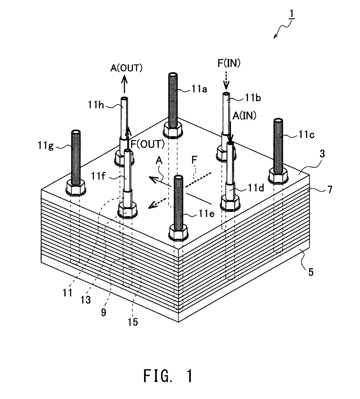
[0073]As shown in FIG. 1, a planar fuel cell apparatus (hereinafter, may be referred to merely as “fuel cell apparatus”) 1 of the first embodiment generates electricity by use of fuel gas (e.g., hydrogen) and oxidizer gas (e.g., air, more specifically oxygen contained in air) supplied thereto.

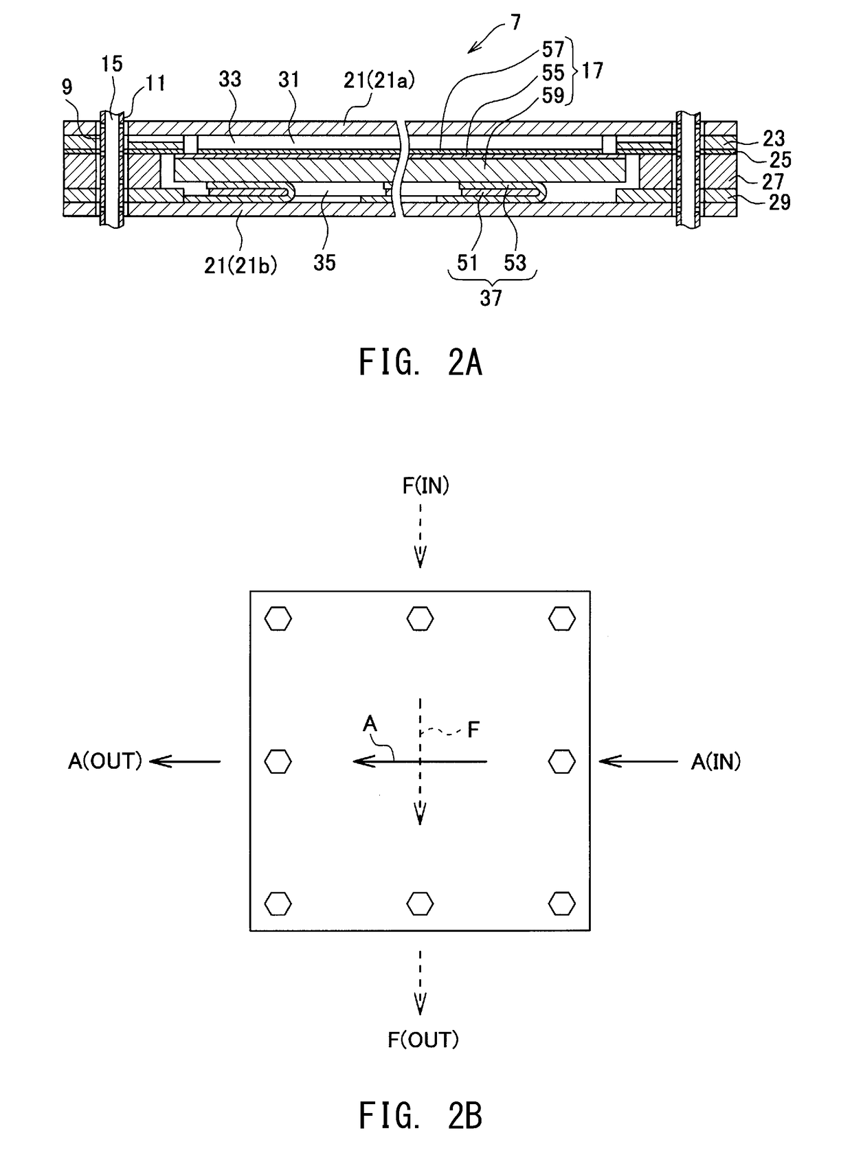
[0074]In the drawings, oxidizer gas is denoted by “A,” and fuel gas is denoted by “F.” Also, “IN” indicates that gas is introduced, and “OUT” indicates that gas is discharged. Further, for convenience of description, directions such as “upper” and “lower” are mentioned on the basis of directions in the drawings, but are not intended to specify the directivity of an actual fuel cell apparatus.

[0075]The fuel cell apparatus 1 of the first embodiment is a planar (rectangular parallelepiped) solid oxide fuel cell apparatus and is a fuel cell stack configured such that a plurality of (e.g...

second embodiment

[0147]Next, a second embodiment will be described; however, the description of contents similar to those of the first embodiment is omitted. In the following description, structural members similar to those of the first embodiment are denoted by the same reference numerals as those of the first embodiment.

[0148]The fuel cell apparatus 1 of the second embodiment meets the following “flow channel disposition condition 2” as well as “flow channel disposition condition 1” of the first embodiment with respect to the oxidizer gas flow channel and the fuel gas flow channel.

[0149]Specifically, in the fuel cell apparatus 1 of the second embodiment, as shown in FIG. 6, as viewed in the stacking direction, the centroid Cfo of the fuel gas outlets Fout is disposed at a position offset from the reference line Lf toward the boundary line Lfp by a distance of 0.3 Xp to Xp; the centroid Cai of the oxidizer gas inlets Ain is disposed at a position located a distance of 0.1 Yp or less from the refere...

third embodiment

[0152]Next, a third embodiment will be described; however, the description of contents similar to those of the first embodiment is omitted. In the following description, structural members similar to those of the first embodiment are denoted by the same reference numerals as those of the first embodiment.

[0153]The fuel cell apparatus 1 of the third embodiment meets the following “flow channel disposition condition 3” as well as “flow channel disposition condition 1” of the first embodiment with respect to the oxidizer gas flow channel and the fuel gas flow channel.

[0154]Specifically, in the fuel cell apparatus 1 of the third embodiment, as shown in FIG. 7A, as viewed in the stacking direction, the centroid Cfo of the fuel gas outlets Fout is disposed at a position located a distance of 0.1 Xp or less from the reference line Lf toward the boundary line Lfp or a distance of 0.1 Xm or less from the reference line Lf toward the boundary line Lfm; the centroid Cai of the oxidizer gas inl...


PUM

PropertyMeasurementUnit
distanceaaaaaaaaaa
distanceaaaaaaaaaa
temperatureaaaaaaaaaa

Abstract

A planar fuel cell apparatus (1) characterized in that, as viewed in a stacking direction, a first rectilinear line which connects a centroid Cfi of fuel gas inlets and a centroid Cfo of fuel gas outlets, and a second rectilinear line which connects a centroid Cai of oxidizer gas inlets and a centroid Cao of oxidizer gas outlets cross each other. That is, the planar fuel cell apparatus employs cross-flow design in which a fuel gas flow channel and an oxidizer gas flow channel cross each other. In the planar fuel cell apparatus of the cross-flow design, as viewed in the stacking direction, the centroid Cfo of the fuel gas outlets is located closer to the centroid Cai of the oxidizer gas inlets than to the centroid Cao of the oxidizer gas outlets.

Description

TECHNICAL FIELD[0001]The present invention relates to a flat plate type fuel cell (hereinafter referred to as a “planar fuel cell apparatus”) which includes a single fuel cell having an anode layer, a cathode layer, and a solid electrolyte layer sandwiched therebetween.BACKGROUND ART[0002]A conventionally known fuel cell apparatus is, for example, a solid oxide fuel cell (hereinafter, may be referred to as SOFC) apparatus which uses solid electrolyte (solid oxide).[0003]The SOFC apparatus uses, for example, a planar single fuel cell having an anode layer provided on one side of a solid electrolyte layer and in contact with fuel gas, and a cathode layer provided on the other side of the solid electrolyte layer and in contact with oxidizer gas (e.g., air).[0004]A fuel gas chamber into which fuel gas is introduced is provided on an anode layer side of the single fuel cell, and an oxidizer gas chamber into which oxidizer gas is introduced is provided on a cathode layer side of the singl...

Claims


Application Information

Patent Timeline
Patent Type & Authority Applications(United States)
IPC IPC(8): H01M8/24H01M8/1007H01M8/10H01M8/12
CPCH01M8/24H01M8/1007H01M8/10H01M8/12H01M8/0271H01M2008/1293H01M8/2483H01M8/2432Y02E60/50H01M8/0258
Inventor YOSHIZAKI, HIROTOSHISHICHIDA, TAKAFUMI
Owner MORIMURA SOFC TECH CO LTD
Why Eureka
Try Eureka