Relative Response Systems and Measuring Methods

Inactive Publication Date: 2019-02-07
ECKBLAD MICHAEL Z +1
View PDF0 Cites 11 Cited by
  • Summary
  • Abstract
  • Description
  • Claims
  • Application Information

AI Technical Summary

Benefits of technology

[0013]This invention is unique in that it combines wireless mesh networking technology and independent programming and reprogramming, using socketable “codelets”, that serve to re-configure functions of autonomous microprocessor-based “radio node pods” on the fly. The radio node pods are organized into mesh networks that have the capacity to setup, initiate and measure a sequence of events involving one to a plurality of individual trainees or teams relative to each other and/or relative to an absolute reference. Any of the radio node pods of a mesh network of the system can command, initiate, and sense stimulus-response sequence events (SRS) at any time, effectively making a system whose characteristic functions can be changed by instantly installing a series of mini-programs termed here “codelets”. In simple embodiments, these codelets can be iterated to provide a repetitive loop of system functi

Problems solved by technology

Measuring a biological reaction to a stimulus is currently problem specific, difficult or impossible to reconfigure, and involves wired data transmission and interconnectivity that interferes with movement.
These limitations restrict the ability of coaches, scientists and individuals to understand and optimize the performance of individuals or teams in a general way, whether it be a response of a boxer to a light or a punch coming his way, or relative reaction times and velocities of throws and catches on a baseball team, for example.
The homemade method suffers from the issues of being non-standardized and having a high variability of accuracy.
Further, they lack the flexibility to be re-programmed at any time to perform a completely different function and to accommodate any type of sensor and stimulus hardware configurations not previously considered in the initial design.
Further, they lack the flexibility to be re-programmed at anytime to perform a completely different function and to accommodate any type of sensor and stimulus hardware configurations not previously considered in the initial design.
Th

Method used


Image

  • Relative Response Systems and Measuring Methods
  • Relative Response Systems and Measuring Methods
  • Relative Response Systems and Measuring Methods

Examples


example i

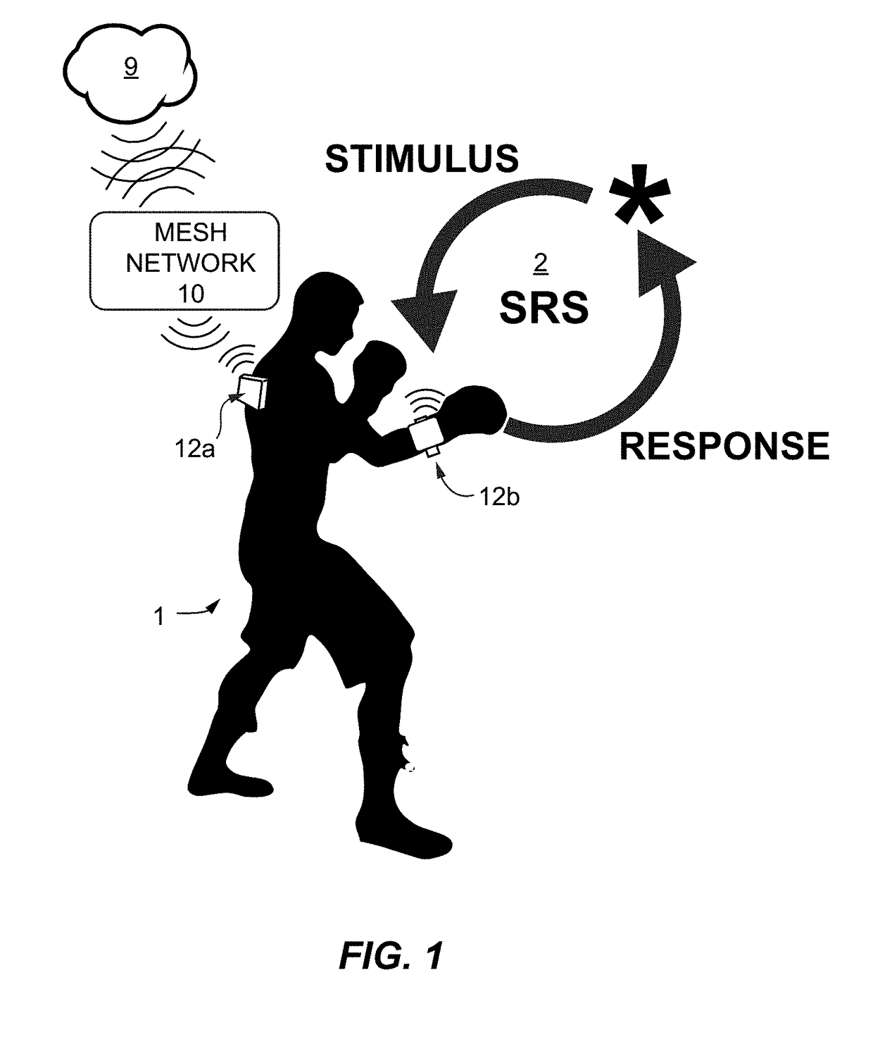
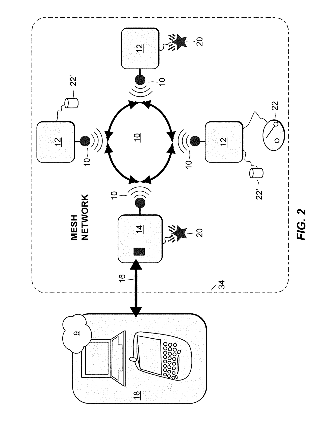
[0152]FIG. 20 is a spatial view of a mesh network with two contestants, and points out that the SRS routines may be extended to multiple subjects. In this example of a complete system and its use in multi-subject play, each user may be wearing multiple miniature radio node pods and will interact with the sensor packages of several other radio node pods. Each blow becomes a stimulus for a next blow, and each response becomes a stimulus for a next response.

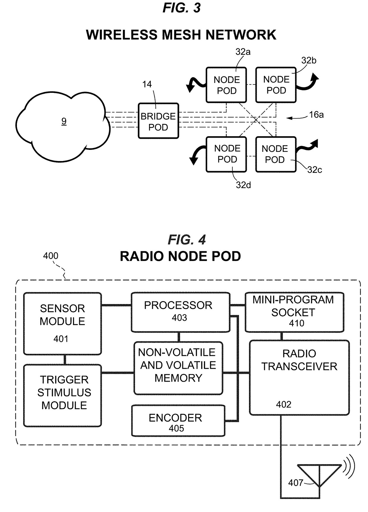
[0153]Communications between a radio node pod and a bridge pod (generalized here as a “gateway pod 140”) extend to a cloud server 9. The gateway pod serves as a portal to a cloud host with remote server operated to display contest results on a leader board as may be used for competition, tourneys, and for team training. Team training may involve systems and methods for collecting reaction data of multiple individuals in response to one or more stimuli. Wireless networking and systems for sensing, quantitating, and processing reactio...

example ii

[0157]In a second example, a system is built around an accelerometer sensor package having a dynamic range in the tens or hundreds of G's. A trigger stimulus device, initially a colored LED, was mounted in a glove and was presented to a subject. As was observed, the subject punches at a target and the mitt-holder braces against the punch. The target device embedded in the glove has an array of sensors to more precisely quantitate precision of the hit and the impact intensity. This system has been demonstrated to sports clubs, dojos and home users and is found to function reliably in a mesh network configuration. Python was used to code the mini-scripts provided over a wireless network on the fly to the processors of the mesh network.

[0158]A calibration system was used to achieve accurate relative results without the need for complex transfer functions.


PUM


Abstract

Mesh networks of radio node pods for measuring performance of teams and individual athletes by first stimulating and then by measuring a parameter of motion selected from velocity, vector, acceleration, force, and rebound. The system includes one or more radio node pods, each radio node pod having a microprocessor, supporting circuitry, a machine layer with one or more sensors and actuators, firmware for essential functions, and a soft socket for receiving “codelets” on the fly, each codelet containing a soft mini-script and attendant variables for iteration of a stimulus-response-sequence (SRS) customized to a previous iteration or training goal. Radio node pods may work in clusters and are typically multipotent, each pod performing specialized functions as dictated by a resident codelet but otherwise all pods having the same or similar hardware. Shared resources, either internal or external to the mesh network, are used for data analysis. Thus a single pod may trigger a stimulus to a user, and another pod may record a response, but are interchangeable, and each response may be a stimulus to trigger another SRS. Communications with an external administrative network or cloud host is generally delegated to a bridge pod dedicated as a gateway or portal. Each individual subject or team is assessed for performance metrics by which a stimulus results in a qualitative or parametric response. According to current best practice, radio pod nodes are synchronized in each mesh network and wirelessly report raw data and/or derived data to an administrative module for reporting, display and recordation. Relative performance of individuals or teams can be tracked or trended to detect weaknesses and improve workout, sports, military training performance, and contests can also be scored using these systems.

Description

CROSS REFERENCE TO RELATED APPLICATIONS[0001]The present application is a Continuation-in-Part of co-pending U.S. patent application Ser. No. 12 / 460,750, filed 24 Jul. 2009, which claims priority under 35 U.S.C. § 119(e) from U.S. Prov. Pat. Appl. Ser. No. 61 / 135,779, filed 24 Jul. 2008, said patent documents being incorporated herein in entirety for all purposes by reference and for which benefit of a chain of priority is hereby claimed.GOVERNMENT SUPPORT[0002]Not applicable.TECHNICAL FIELD[0003]The present invention relates to systems and methods for wirelessly collecting reaction data of a subject individual or a team to stimuli and, more particularly, to using autonomous radio node pod clusters as a mesh network for sensing and processing behavioral responses by first stimulating and then by measuring and reporting a performance metric.BACKGROUND[0004]Measuring a biological reaction to a stimulus is currently problem specific, difficult or impossible to reconfigure, and involves...

Claims


Application Information

Patent Timeline
IPC IPC(8): A63B24/00H04W84/12G06F8/40
CPCA63B24/0006A63B24/0062H04W84/12G06F8/40A63B2225/50A63B2220/30A63B2220/40A63B69/32A63B71/0616A63B71/145G09B19/0038A63B2071/0655A63B2220/12A63B2220/53A63B2220/801A63B2220/803A63B2220/836A63B2225/20G06F9/45529G06F9/54A61B5/02007A61B5/02416A63B2071/0675A63B2220/62G07C1/28G06V40/23
Inventor ECKBLAD, MICHAEL Z.DEMILE, KENNETH
Owner ECKBLAD MICHAEL Z
Why Eureka
Try Eureka