Variable geometry def mixer design

a mixer design and variable geometry technology, applied in the field of mixers, can solve the problems of increased turbulence, increased turbulence, and mixer design based on low exhaust flow may not be the optimal mixer design for high exhaust flow conditions

Inactive Publication Date: 2019-02-07
INT ENGINE INTPROP CO LLC
View PDF4 Cites 3 Cited by
  • Summary
  • Abstract
  • Description
  • Claims
  • Application Information

AI Technical Summary

Benefits of technology

[0007]The use of a Variable Geometry DEF Mixer, such as one using movable geometry defining components such as movable mixer blades or movable vanes that may be adjusted based, for example, upon engine exhaust flow conditions, allows for optimal reductant and exhaust mixing performance over all or at least a much larger proportion of exhaust gas flow conditions that may be experienced under real-world drive or operating cycles. The movable geometry defining components are mechanically adjusted by way of a change in angle and / or position, so that optimal mixing is achieved based, for example, on exhaust flow, temperature, and reductant dosing quantity. At least one actuator actuates the mechanical adjustment, and may be pneumatic, electric, or hydraulic in nature, as non-limiting examples. Mechanical adjustment of the movable geometry defining components may further depend upon other factors, such as a current, pending, or recent particulate filter regeneration event, or other engine, vehicle, location, topographical, or environmental information.
[0008]More specifically, embodiments of the Variable Geometry DEF Mixer utilizing at least one movable mixer blade use at least one actuator to increase or decrease the angle of the at least one mixer blade within the mixer device, thereby extending the at least one mixer blade further into the exhaust flow or retracting the at least one mixer blade further out of the exhaust flow, respectively. Further embodiments of the Variable Geometry DEF Mixer utilizing at least one movable mixer blade may extend the at least one mixer blade further into the exhaust flow under conditions of low exhaust flow, resulting in increased swirl and rotation of the exhaust flow, thereby improving breakup of reductant droplets and mixing of the reductant with the exhaust. Such conditions of low exhaust flow may be encountered when the engine to which the engine exhaust aftertreatment system is connected is operating at a low power and / or speed, for example in the lower half of the engine's power and / or speed operating range. Further embodiments of the Variable Geometry DEF Mixer utilizing at least one movable mixer blade may retract the at least one mixer blade out of the exhaust flow under conditions of high exhaust flow, resulting in decreased swirl and rotation of the exhaust flow, but also reducing exhaust flow restriction. Such conditions of high exhaust flow may be encountered when the engine to which the engine exhaust aftertreatment system is connected is operating at a high power and / or speed, for example in the upper half of the engine's power and / or speed operating range.
[0009]Similarly, embodiments of the Variable Geometry DEF Mixer utilizing at least one set of movable vanes use at least one actuator to increase or decrease the angle of the at least one set of movable vanes within the mixer device, thereby skewing the at least one set of movable vanes with respect to the exhaust flow or aligning the at least one set of movable vanes with respect to the exhaust flow, respectively. Further embodiments of the Variable Geometry DEF Mixer utilizing at least one set of movable vanes may increase the angle of the at least one set of movable vanes within the mixer device under conditions of low exhaust flow, resulting in increased turbulence and thereby improving breakup of reductant droplets and mixing of the reductant with the exhaust. Further embodiments of the Variable Geometry DEF Mixer utilizing at least one set of movable vanes may decrease the angle of the at least one set of movable vanes within the mixer device under conditions of high exhaust flow, resulting in decreased turbulence, but also reducing exhaust flow restriction.
[0010]Further embodiments of the Variable Geometry DEF Mixer utilizing at least one set of movable vanes may use at least one set of upstream movable vanes and at least one set of downstream movable vanes, and may rotate the movable vanes of the upstream set and of the downstream set out of alignment with the exhaust flow in opposite directions under conditions of high exhaust flow, further increasing turbulence, reductant droplet breakup, and mixing of the reductant with the exhaust. The embodiments of the Variable Geometry DEF Mixer utilizing at least one set of upstream movable vanes and at least one set of downstream movable vanes may further rotate the movable vanes of the upstream set and of the downstream set into alignment with the exhaust flow under conditions of low exhaust flow, reducing turbulence, but also reducing exhaust flow restriction. Further embodiments of the Variable Geometry DEF Mixer using movable geometry defining components, such as movable mixer blades or movable vanes, may also be provided with at least one fixed geometry defining component, such as a fixed helical ramp or corkscrew, or other turbulence causing device.
[0014]The Variable Geometry DEF Mixer has the ability to optimize reductant mixing in an exhaust stream over a wider range of exhaust flow rates. Components of the Variable Geometry DEF Mixer are robust and may be designed to last the entire lifetime of a vehicle.

Problems solved by technology

While this helps to make diesel engines efficient, it also results in the formation of nitrogen oxides (NOx), an undesirable pollutant, during the combustion process.
Unfortunately, an optimal mixer design based on conditions of low exhaust flow may not be an optimal mixer design for conditions of high exhaust flow.
Further embodiments of the Variable Geometry DEF Mixer utilizing at least one set of movable vanes may increase the angle of the at least one set of movable vanes within the mixer device under conditions of low exhaust flow, resulting in increased turbulence and thereby improving breakup of reductant droplets and mixing of the reductant with the exhaust.

Method used


Image

  • Variable geometry def mixer design
  • Variable geometry def mixer design
  • Variable geometry def mixer design

Examples


Embodiment Construction

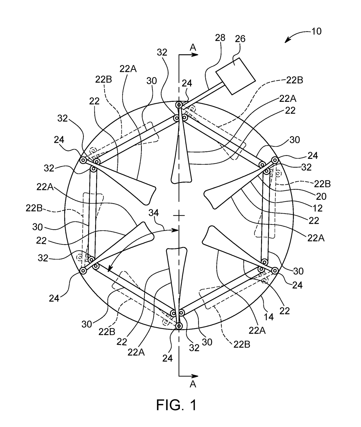
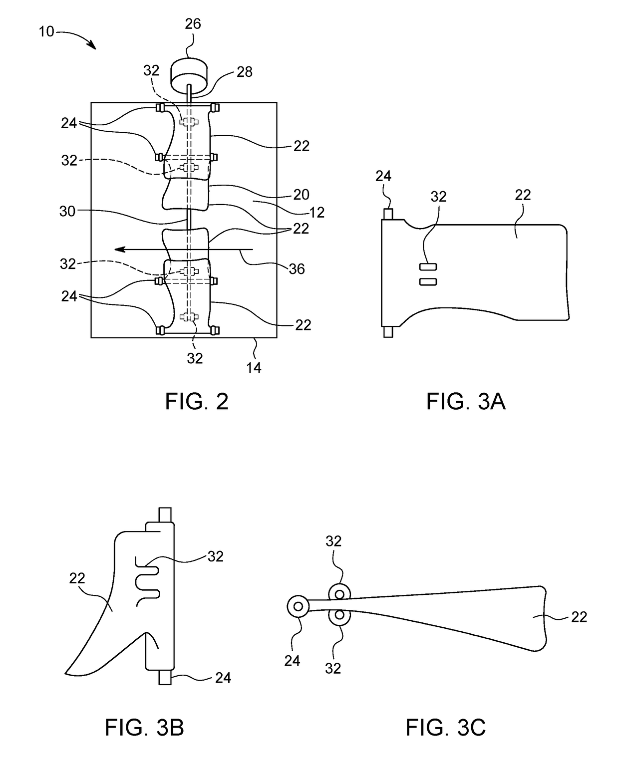
[0026]Referring now to FIGS. 1 and 2, a top view and a sectional view taken along line A-A, respectively, of an embodiment of a Variable Geometry DEF Mixer is shown. A DEF mixer 10 includes a mixing pipe 14 having within it a mixing device 12, which, in the embodiment shown in FIGS. 1 and 2, is a multiple blade mixer 20. Movable mixer blades 22 are connected to the mixing pipe 14 using mixer blade pivot points 24, which may be provided as vertical hinges as shown. A blade actuator 26 is connected to one of the movable mixer blades 22 by way of a blade actuator linkage 28 that passes through the wall of the mixing pipe 14. Angular movement of the movable mixer blades 22 is actuated and coordinated using an inter-blade linkage 30. Each of the links of the blade actuator linkage 28 and of the inter-blade linkage 30 is connected to the movable mixer blades 22 using a blade linkage connection 32.

[0027]The DEF mixer 10 uses the blade actuator 26 to increase or decrease the blade angle 34 ...


PUM


Abstract

A variable geometry mixer for mixing reductant with engine exhaust includes at least one movable mixer blade or set of movable vanes. The variable geometry mixer is operable to extend the mixer blade(s) into the flow of exhaust under low exhaust flow conditions and to retract the mixer blade(s) out of the flow of exhaust under high exhaust flow conditions, or to increase the angle of the movable vanes under low exhaust flow conditions and to decrease the angle of the movable vanes under high exhaust flow conditions. The movable mixer blade(s) may adjoin at least one fixed geometry defining component. Control of the angle or position of the mixer blade(s) or movable vanes may be based on exhaust flow conditions, exhaust temperature, reductant dosing quantity, a particulate filter regeneration event, vehicle information, vehicle engine information, vehicle location, topographical information, and / or environmental information.

Description

BACKGROUNDField of Invention[0001]Embodiments described herein generally relate to a mixer for causing a reductant such as urea to more completely evaporate in an engine exhaust flow by generating swirling exhaust gas flow under low exhaust flow conditions, while minimizing flow restriction under high exhaust flow conditions.Related Art[0002]Diesel engines commonly operate with a lean air to fuel ratio, so that only part of the available oxygen is used in the fuel combustion reaction. While this helps to make diesel engines efficient, it also results in the formation of nitrogen oxides (NOx), an undesirable pollutant, during the combustion process. Presently, the Environmental Protection Agency (EPA) regulates the amount of NOx that may be emitted in vehicle exhaust, so that vehicle and engine manufacturers employ various techniques to reduce NOx emissions.[0003]A common technique to reduce NOx tailpipe emissions involves the use of Selective Catalytic Reduction (SCR). SCR works by ...

Claims


Application Information

Patent Timeline
Patent Type & Authority Applications(United States)
IPC IPC(8): F01N3/28F01N3/20B01F5/06
CPCB01F2005/0622F01N3/2892F01N3/208B01F5/0611F01N2240/20G07C5/006G07C5/008G07C5/0816B60R16/0232B01F25/4311B01F25/43171
Inventor ADELMAN, BRADLEY JAYBRENNEMAN, SETH ULRICH
Owner INT ENGINE INTPROP CO LLC
Why Eureka
Try Eureka