Energy harvesting substrate network and communication apparatus

a technology of energy harvesting substrate and communication apparatus, applied in the direction of transmission, radiating element structure, independent non-interfering antenna combinations, etc., can solve the problems of poor weather on microwaves, achieve the effect of reducing the pressure effect, eliminating acoustic interference signals, and improving transmission and receiving of transmitted information

Inactive Publication Date: 2019-02-21
TABE JOSEPH AKWO
View PDF3 Cites 33 Cited by
  • Summary
  • Abstract
  • Description
  • Claims
  • Application Information

AI Technical Summary

Benefits of technology

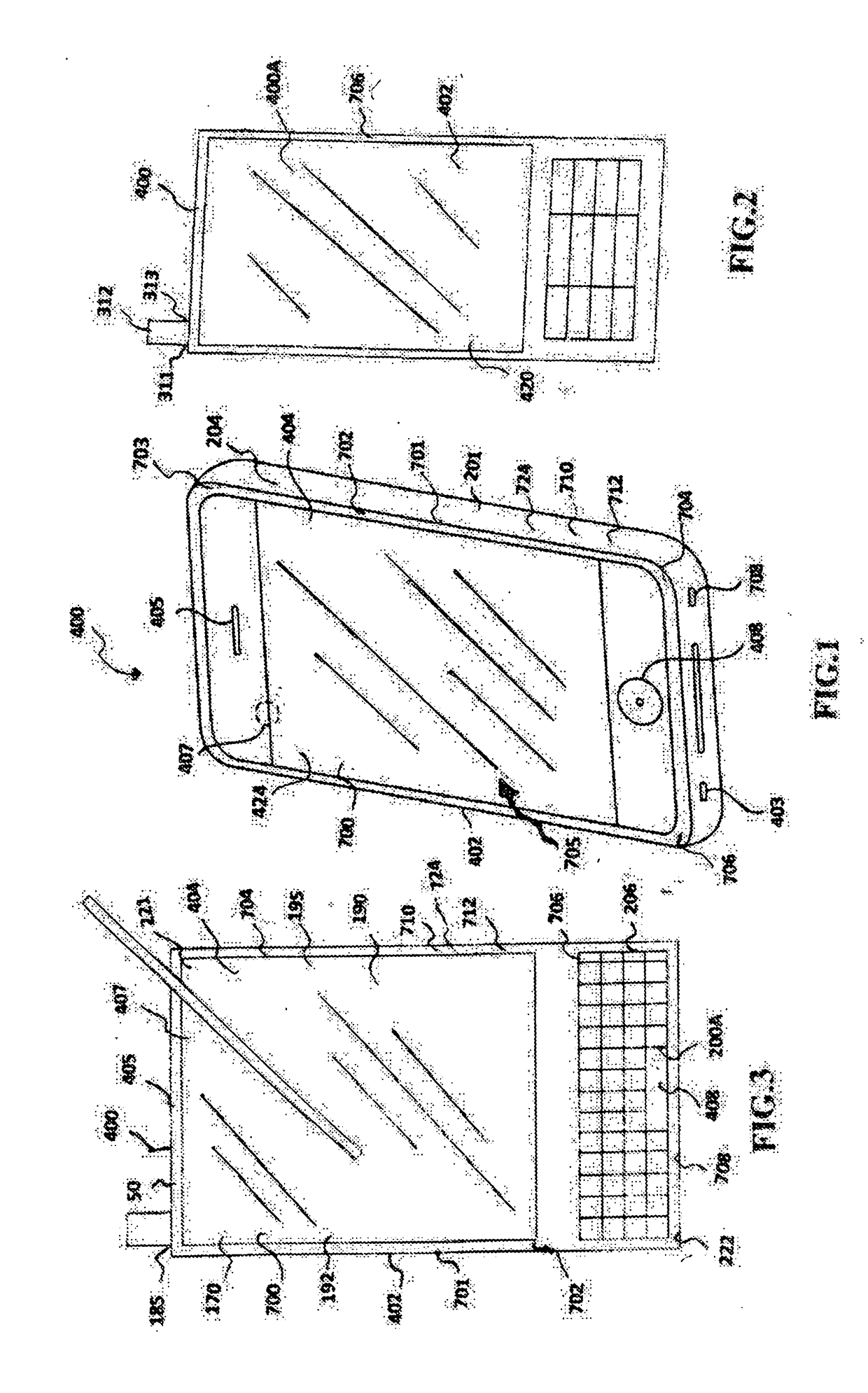
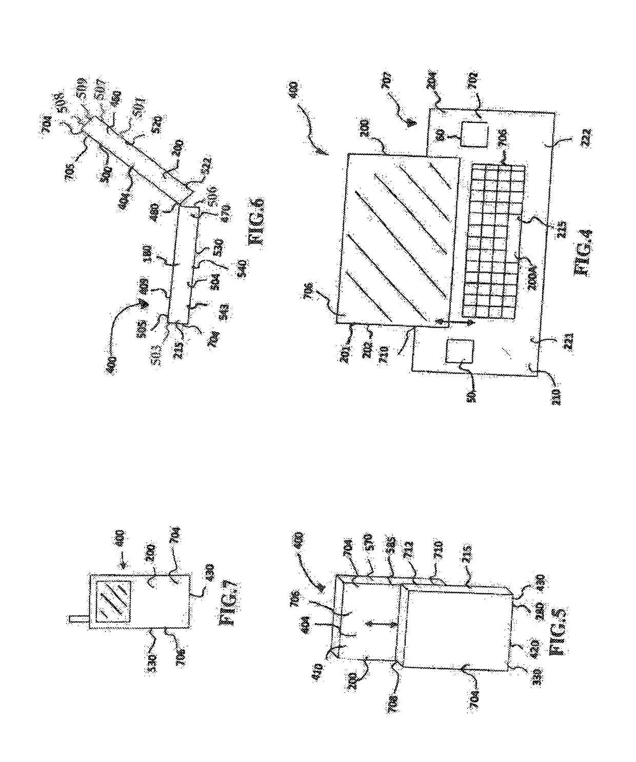
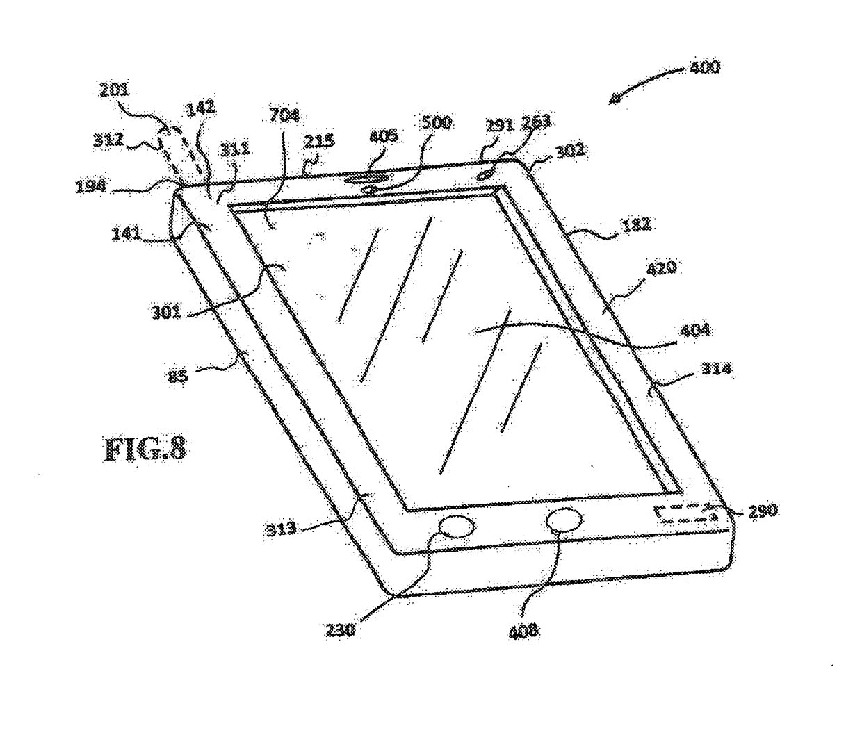
[0049]Disclosed embodiments provide communication apparatus operable for reduction of the pressure effect to improve the transmission and receiving of the transmitted information. The antenna is made up of cell foams and would allow the media device and the cell phone to operate on the same mast mounted antenna. The antenna is operable to receive and transmit coded information. The antenna is communicatively configured with the chip for eliminating acoustic interference signal radiation problems that exist in the wave traffic. The quality features of the antenna include stainless steel ferrule, high-gloss urethane finish over fiberglass, powerful brass internal elements, ferrite choke bead, and UV stable RG-8x marine cable with a factory-installed mini-connector. Embodiments provide antenna apparatus operable to reduce the whistling effects and also to damp the occurring wave due to vibration. Certain embodiments provide antenna apparatus communicatively connected to a chip in communication with a logic circuit. Other embodiments of the disclosure provide an antenna motor which is turned on when the ignition switch of a vehicle is turned on. When the ignition switch is turned on, the circuit for the antenna motor will be closed and the antenna motor will rotate on one direction, enabling the antenna to be raised up.
[0050]Disclosed embodiments provide antenna apparatus with a stronger link operable with wireless communication devices and/or with vehicle media device to oversee any weak signal and to improve communication clarity. The antenna could be embedded or be vertically mounted at ranges from 4″ to 24″ with ultimate signal pulling power. All internal elements are sealed with fiberglass rod coated with high-gloss urethane finish. The high-gloss urethane coating is to ensure lasting performance and more compatibility with the other high quality antenna products that could be used. Certain embodiments of the disclosure provide an antenna apparatus operatively connected to a chip operable at other frequencies. Disclosed embodiments provide improvement to acoustic reduction to enable better communication performance. The communication apparatus is operatively configured for transmitting, receiving, switching and also for transmitting receiving and switching by combining ground to air to transmit and receive signals with the incorporation of a processor configured for processing digital signal.
[0051]Embodiments provide a communication apparatus operatively configured for communications and network applications. The communication apparatus is disposed with signal booster to boost signal reception strength for cell phone and network applications. The communication apparatus is further disposed with substrates to convert sound waves, vibrations, solar energy, and pressure force into electrical energy communicable to battery cell. Disclosed embodiments provide improved communication apparatus comprising media device, computer device, cell phone device, and hands-free cell phone and Internet usage while dri

Problems solved by technology

The chip is further operable to prevent wireless signal radiation, reducing exposure to cellular radio signals, which

Method used


Image

  • Energy harvesting substrate network and communication apparatus
  • Energy harvesting substrate network and communication apparatus
  • Energy harvesting substrate network and communication apparatus

Examples


Embodiment Construction

[0138]The terminology used herein is for the purpose of describing particular embodiments only and is not intended to be limiting of embodiments. As used herein, the singular forms “a”, “an”, “at least”, “each”, “one of”, and “the” are intended to include the plural forms as well, unless the context clearly indicates otherwise.

[0139]It would be further understood that the terms “include”, “includes” and / or “including”, where used in this specification, specify the presence of stated features, integers, steps, operations, elements, and / or components, but do not preclude the presence or addition of one or more other features, integers, steps, operations, elements, components, and / or groups thereof. In describing example embodiments as illustrated in the drawings, specific terminology is employed for the sake of clarity. However, the disclosure of this patent specification is not intended to be limited to the specific terminology so selected and it is to be understood that each specifi...


PUM


Abstract

Embodiments encompasses 6th and 5th generation broad network and communications technology, including next generation “G5, G6, Gn and N.” The G5, G6, Gn and N comprises BETTER network disposed with metamaterial substrate, plasmonic substrate, fluorescent substrate, and photonic substrate for optical network and data center applications. The network configured with multiple antennas on chip for communications, energy harvesting, and interactive user interface applications. The chip configured to boost signal receptions and to provide faster data transmission speed. Embodiments encompass three communication modes—the Cell phone, wireless network applications, and Global communication and media information. Embodiments provide communication apparatus to enhance mobile communication efficiency. The network disposed with charging circuit board configured with memories, processors, sensors, and modules. Embodiments further provide the communication apparatus comprising gaming device, wireless media configured with sensors embedded in silicon substrate and fused in nano-fiber/microfiber material having excellent electrical characteristics for voice enabled and texting applications.

Description

[0001]I HEREBY CLAIM PRIORITY BENEFITS FROM APPLICATION Ser. No. 13 / 004,912, filed Jan. 12, 2011, which claims priority benefit from U.S. patent application Ser. No. 13 / 328,383, filed Dec. 16, 2011, which claims priority benefit from U.S. patent application Ser. No. 12 / 910,833, filed Oct. 24, 2010, which claims priority benefit from U.S. patent application Ser. No. 12 / 852,481, filed Aug. 7, 2010, which claims priority benefit from U.S. patent application Ser. No. 12 / 795,567, filed Jun. 7, 2010, currently allowed, which claims priority benefit from U.S. patent application Ser. No. 11 / 475,286, filed on Feb. 28, 2006, now U.S. Pat. No. 7,769,342, which is a continuation in part of U.S. patent application Ser. No. 10 / 814,087, filed on Mar. 31, 2004, now U.S. Pat. No. 7,116,942, which is a continuation in part of U.S. patent application Ser. No. 09 / 559,330, filed Apr. 12, 2000, now U.S. Pat. No. 6,782,240, which claims priority benefit from provisional application Ser. No. 60 / 131,134, fi...

Claims


Application Information

Patent Timeline
IPC IPC(8): H01Q1/24
CPCH01Q1/243H01Q1/38H04B7/0413H01Q1/007H01Q1/2283H01Q1/248H01Q21/28H01Q21/30
Inventor TABE, JOSEPH AKWO
Owner TABE JOSEPH AKWO
Why Eureka
Try Eureka