Series-Fed E-shaped Patch Antenna Array with Co-polarized Parasitic Patches

a patch antenna and patch array technology, applied in the field of patch antennas, can solve the problems of complex antenna structure, high manufacturing cost, complex multilayer substrate, etc., and achieve the effect of increasing the aperture efficiency of the antenna, and increasing the overall antenna gain

Active Publication Date: 2019-02-28
KOREA ADVANCED INST OF SCI & TECH
View PDF0 Cites 14 Cited by
  • Summary
  • Abstract
  • Description
  • Claims
  • Application Information

AI Technical Summary

Benefits of technology

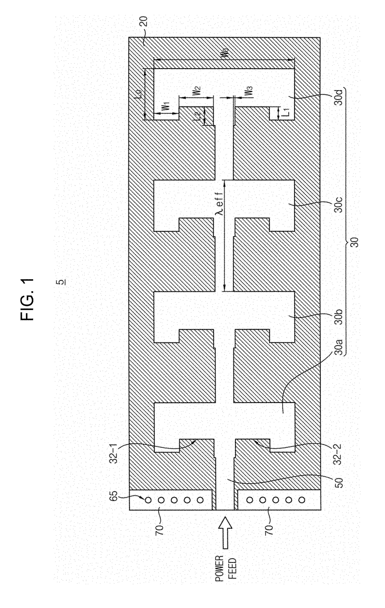
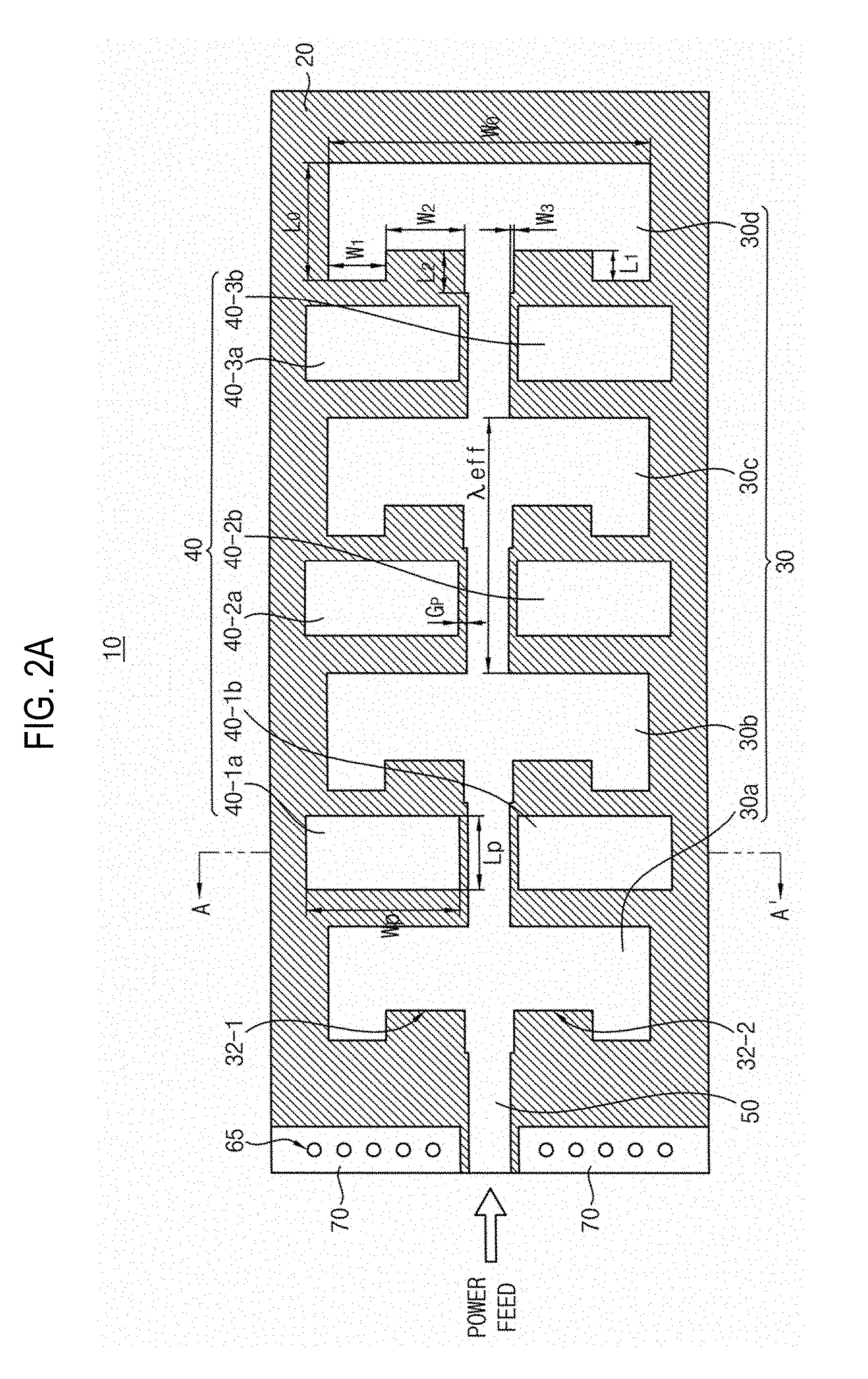
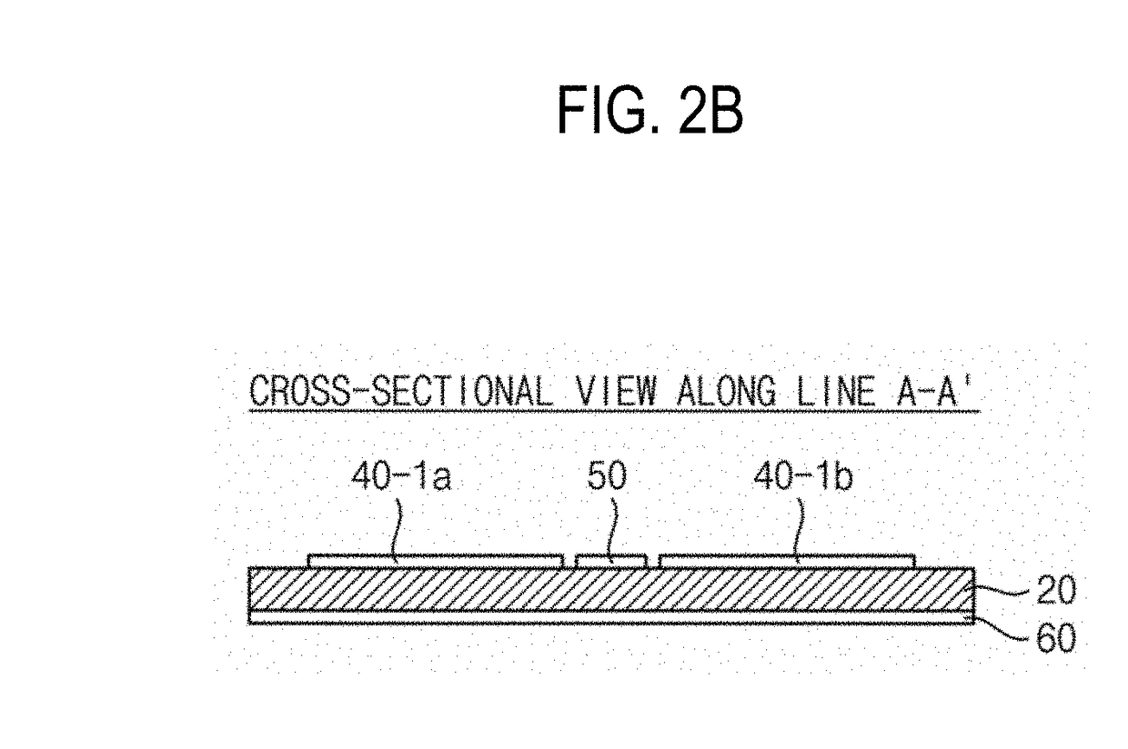
[0022]The parasitic patches added between the E-shaped patch antennas according to the present invention are co-polarized with the E-shaped patch antennas so that the current flows in the parasitic patches have the same polarity as the current flows in the E-shaped patch antennas. The parasitic patches can thus function as additional radiating elements, thereby increasing the overall antenna gain. Since the parasitic patches are disposed between the E-shaped patch antennas, there is no increase in the entire area of the series-fed E-shaped patch antenna array due to the addition of the parasitic patches. The parasitic patches can provide an increased gain at a frequency higher than the resonance frequency of the E-shaped patch for a given antenna area. Further, the parasitic patches can increase the aperture efficiency of the antenna. Also, since the parasitic patches compensate for the gain at the high frequency edge, the gain flatness of the microstrip patch antenna array employing them can be increased.

Problems solved by technology

The multilayer substrate is more complicated in the production process than the single layer substrate, and thus has a high manufacturing cost.
The antenna designs using such a multilayer substrate has serious drawbacks in that they incur high manufacturing costs and require a complex antenna structure.
However, most 60 GHz antennas have poor gain flatness over 3 dB in the 60 GHz unlicensed band.

Method used


Image

  • Series-Fed E-shaped Patch Antenna Array with Co-polarized Parasitic Patches
  • Series-Fed E-shaped Patch Antenna Array with Co-polarized Parasitic Patches
  • Series-Fed E-shaped Patch Antenna Array with Co-polarized Parasitic Patches

Examples


Embodiment Construction

[0033]Various example embodiments will be described more fully hereinafter with reference to the accompanying drawings, in which some example embodiments are shown. The present inventive concept may, however, be embodied in many different forms and should not be construed as limited to the example embodiments set forth herein. Rather, these example embodiments are provided so that this disclosure will be thorough and complete, and will fully convey the scope of the present inventive concept to those skilled in the art. In the drawings, the sizes and relative sizes of layers and regions may be exaggerated for clarity. Like numerals refer to like elements throughout.

[0034]It will be understood that, although the terms first, second, third etc. may be used herein to describe various elements, these elements should not be limited by these terms. These terms are used to distinguish one element from another. Thus, a first element discussed below could be termed a second element without de...


PUM


Abstract

A series-fed E-shaped patch antenna array has co-polarized parasitic patches to improve aperture efficiency. Each of microstrip parasitic patches is inserted between a plurality of microstrip E-shaped patch antennas. The parasitic patches are co-polarized with the E-shaped patch antennas so that the current flows in the parasitic patches and the E-shaped patch antennas have the same polarity. Additional radiation from the co-polarized microstrip parasitic patches significantly improves gain flatness, gain and aperture efficiency due to offset resonance frequency.

Description

CROSS-REFERENCE TO RELATED APPLICATION[0001]This U.S. non-provisional application claims priority under 35 USC § 119 from Korean Patent Application No. 10-2017-0109848, filed on Aug. 30, 2017 in the Korean Intellectual Property Office (KIPO), the disclosure of which is hereby incorporated by reference in its entirety.BACKGROUND1. Technical Field[0002]The present invention relates to an antenna technology field, and more particularly, to a patch antenna.2. Description of the Related Art[0003]For example, The 60 GHz international unlicensed band as wide as 57-66 GHz is being commercialized for several-Gb / s high data-rate communication and ultrahigh definition video streaming. For this frequency band, one of the key research topics is to develop a high gain antenna array that can mitigate the severe path loss during propagation in the air.[0004]In general, many designs proposed to date to address this issue are composed of multilayered substrate including low temperature co-fired ceram...

Claims


Application Information

Patent Timeline
Patent Type & Authority Applications(United States)
IPC IPC(8): H01Q21/06H01Q21/00
CPCH01Q21/0075H01Q9/0421H01Q21/065H01Q9/0407H01Q19/005H01Q21/08H01Q5/385
Inventor PARK, CHUL-SOONJANG, TAE-HWANKIM, HONG-YI
Owner KOREA ADVANCED INST OF SCI & TECH
Why Eureka
Try Eureka