Eureka AIR delivers breakthrough ideas for toughest innovation challenges, trusted by R&D personnel around the world.

Motor drive device including pwm converter controlled in boosting ratio

Active Publication Date: 2019-02-28
FANUC LTD
View PDF9 Cites 5 Cited by
  • Summary
  • Abstract
  • Description
  • Claims
  • Application Information

AI Technical Summary

Benefits of technology

The patent text is discussing a problem with motor drive devices that use PWM converters. Increasing the boosting ratio of the PWM converter to control it can result in a long power failure time, but it also generates a lot of heat. Conversely, when the boosting ratio is set too low, the motor may fail quickly, but it may generate less heat. The text suggests a solution to address this problem: using a low-cost, small-footprint PWM converter that can handle long power failure times and minimal heat generation. This approach may require increasing the capacitance of the DC link capacitor or adding a UPS to improve the device's reliability.

Problems solved by technology

When supply of AC power from the AC power supply to the PWM converter is cut off due to power failure, the PWM converter can no longer perform a power conversion operation for converting AC power into DC power, so no DC power is supplied to the DC link.
However, since DC power is stored in the DC link capacitor provided in the DC link, the motor can be driven to a certain extent using AC power output by converting the DC power stored in the DC link capacitor by the inverter, even during the power failure of the AC power supply.
When the PWM converter is controlled at a high boosting ratio in the normal state, if power failure occurs in the AC power supply, since the amount of DC power stored in the DC link capacitor is large at the time of occurrence of the power failure, the allowable power failure time in which the motor can be driven during the power failure of the AC power supply is long.
However, disadvantageously, heat is generated in large quantities due to the switching losses of the PWM converter and the inverter.
As another disadvantage, heat is generated in large quantities due to resistance components in the motor drive device typified by, e.g., a bleeder resistor, a balancing resistor, and a current limiting resistor for LED lighting, placed on the DC link, and the parasitic resistance of the capacitor.
When the PWM converter is controlled at a low boosting ratio in the normal state, if power failure occurs in the AC power supply, since the amount of DC power stored in the DC link capacitor is small at the time of occurrence of the power failure, the allowable power failure time during the power failure of the AC power supply is disadvantageously short.
However, little heat is generated due to the switching losses of the PWM converter and the inverter, and little heat is generated due to the resistance components on the DC link.
In this manner, the motor drive device including a PWM converter traditionally poses a problem: setting the boosting ratio used to control the PWM converter high results in a long allowable power failure time but in a large amount of heat generated due to the switching losses of the PWM converter and the inverter and the resistance components on the DC link, while setting the boosting ratio low results in a small amount of heat generated due to the switching losses of the PWM converter and the inverter and the resistance components on the DC link but in a short allowable power failure time, and, for example, poses a problem: to prolong the allowable power failure time and reduce the amount of heat generated due to the switching losses of the PWM converter and the inverter and the resistance components on the DC link, the capacitance of the DC link capacitor may be enhanced, or a UPS (Uninterruptible Power Supply) or the like may be additionally used, but such approaches increase the cost and the footprint.

Method used


Image

  • Motor drive device including pwm converter controlled in boosting ratio
  • Motor drive device including pwm converter controlled in boosting ratio
  • Motor drive device including pwm converter controlled in boosting ratio

Examples


Embodiment Construction

[0021]A motor drive device including a PWM converter controlled in boosting ratio will be described below with reference to the drawings. However, it should be understood that the present invention is not limited to the drawings or the following embodiments. In the drawings, the same reference numerals denote the same members. These drawings use different scales as appropriate to facilitate an understanding.

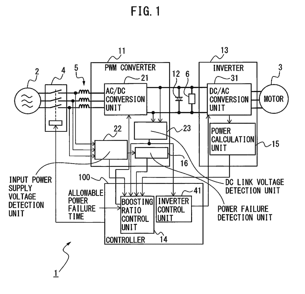
[0022]FIG. 1 is a block diagram illustrating a motor drive device according to one embodiment. The case where an AC motor (simply referred to as a “motor” hereinafter) 3 is controlled by a motor drive device 1 connected to an AC power supply 2 will be taken as an example herein. The numbers of phases of the AC power supply 2 and the motor 3 do not particularly limit this embodiment, and a three- or single-phase configuration, for example, may be used. In the embodiment illustrated in FIG. 1, the AC power supply 2 is implemented as a three-phase AC power supply, and the motor 3 is...


PUM


Abstract

A motor drive device includes a PWM converter configured to convert AC power supplied from an AC power supply into DC power and supply it to a DC link, a DC link capacitor which is provided in the DC link and may store the DC power, an inverter configured to convert the DC power in the DC link into AC power for motor driving and output it, and a boosting ratio control unit configured to control the boosting ratio as the ratio of the value of the DC voltage output from the PWM converter to the peak value of the AC voltage input from the AC power supply, to allow a motor to be driven using AC power output by converting the DC power stored in the DC link capacitor by the inverter during shut-off of supply of the DC power from the PWM converter to the DC link.

Description

BACKGROUND OF THE INVENTION1. Field of the Invention[0001]The present invention relates to a motor drive device including a PWM converter controlled in boosting ratio.2. Description of the Related Art[0002]In a motor drive device which drives motors in a machine tool, forging machinery, an injection molding machine, or various robots, AC power supplied from an AC power supply is temporarily converted into DC power, the DC power is further converted into AC power, and the AC power is used as drive power for the motor provided for each drive axis. The motor drive device includes a converter (rectifier) which rectifies AC power supplied from an AC power supply and outputs DC power, and an inverter which is connected to a DC link on the DC side of the converter and performs mutual power conversion between the DC power of the DC link and the AC power serving as drive power or regenerative power for the motor, and the device controls the speed, the torque, or the rotor position of the mot...

Claims


Application Information

Patent Timeline
IPC IPC(8): H02P27/08H02P29/024
CPCH02P27/08H02P29/024H02P27/00H02P29/025H02P23/06
Inventor KUROKI, WATARU
Owner FANUC LTD
Why Eureka
Eureka Blog
Learn More