Fugitive emission detection

a technology of emission detection and fugitiveness, applied in the direction of instruments, fluid-tightness measurement, measurement of fluid loss/gain rate, etc., can solve the problems of increased maintenance costs, loss of profit/revenue, and inability to eliminate all leakage risks, etc., to achieve more regular maintenance and inspection, high reliability, and less reliability

Active Publication Date: 2019-03-14
ROTORK UK
View PDF0 Cites 0 Cited by
  • Summary
  • Abstract
  • Description
  • Claims
  • Application Information

AI Technical Summary

Benefits of technology

[0047]The skilled person will be aware that various such valve operators are readily commercially available from Rotork PLC group of companies. Advantageously, embodiments of the invention may be easily incorporated into such known devices with only relatively minimal modification.
[0048]The invention is predicated, at least in part, on the Applicants' recognition that the static seals in the valve and / or valve operator are highly reliable (and can nominally be considered to be a perfect seal) whereas a rotating seal such as that provided at the valve stem is unavoidably less reliable (and, therefore, typically requires more regular maintenance and inspection). As such, it is possible to anticipate that the leak path of fugitive emissions from the valve will pass through the valve stem passage (and typically through the rotational seals provided across the passage to close the space between the stem and valve housing) to the valve operator, as the path of least resistance.
[0049]By providing a cavity which is at least partially contiguous, in use, with the valve stem passage, the cavity will receive any such fugitive emissions. Advantageously, embodiments of the invention allow monitoring / detection to be carried out at the valve operator, rather than at the valve itself, which will almost always be in a more convenient and / or readily accessible location. Even though embodiments may allow the detection to be carried out at a more convenient location it is also an advantage that, unlike many prior art methods (such as Infrared Temperature or Acoustic Emissions), embodiments of the invention enable direct testing of leaking fluid.
[0050]Furthermore, it will be appreciated that valve operators are generally easily replaced or upgraded (whereas the valve may be in a flow which needs continuous operation). For example valve operators may generally be configured for attachment onto standardised valve flanges. Thus, a valve operator in accordance with embodiments of the invention may readily be retrofitted to existing industrial valves.

Problems solved by technology

In particular as valves by their nature, necessitate some non-static seals they will present a potential leak location in any industrial flow system.
Valve manufactures are constantly improving their products to reduce the risk but this cannot eliminate all risk of leakage.
Such Leakage may lead to loss of profit / revenue, increased maintenance costs, increased process risk / risk to operators, risk of contamination (to the environment) and / or risk of contamination (to the fluid / product).
Some techniques rely upon manual, labour intensive, detection.
Clearly these methods are labour intensive (often requiring specialist skilled labour), of limited accuracy and time consuming.
However, not all leaks can be detected by this method (some leaks do not cause a measurable temperature differential).
Further the external temperature readings of pipelines and fittings can be influenced by other external factors which may result in a loss of accuracy or even the ability to detect changes related to leaks altogether.
Such systems only provide an indirect indication of leakage and require extensive tailoring to a particular valve.
However, there are clear limitation / difficulties to this approach since listening frequency must be very carefully selected to filter out nearby noise.

Method used


Image

  • Fugitive emission detection
  • Fugitive emission detection
  • Fugitive emission detection

Examples


Embodiment Construction

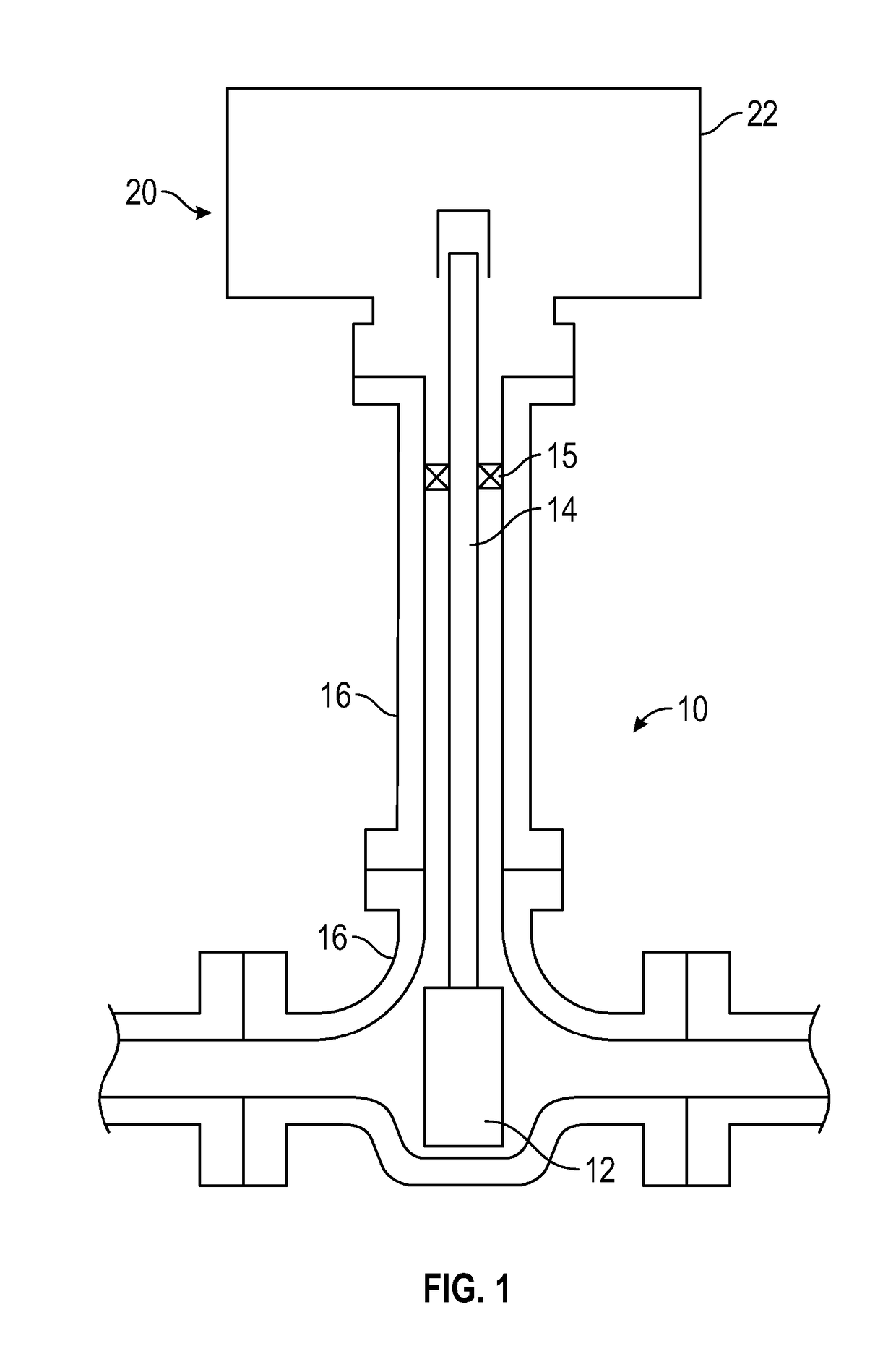
[0104]FIG. 1 shows a typical industrial valve assembly 10 which may be used to control the flow of fluids in industrial applications. For example, the valve assembly 10 could be used oil and gas, water and waste water, power, marine, mining, food, pharmaceutical and chemical industries. The valve assembly comprises a valve 10 including a valve member 12, connected to a valve actuation stem 14. The valve could for example be a quarter turn valve or a multi-turn valve arrangement.

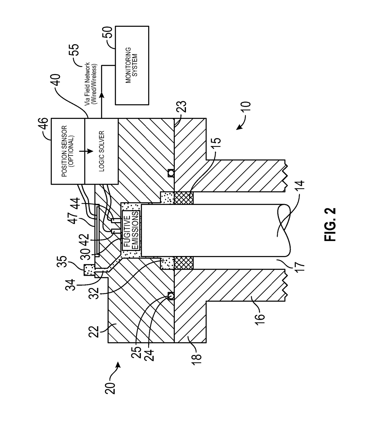
[0105]The valve member 12 and stem 14 are provided within a housing 16. The upper portion of the housing 16 comprises a valve stem passage 17 and terminates at a flange 18. At least one stem seal 15 is provided between the stem passage 17 and stem 14 and is intended to prevent the escape of fluid from the valve housing 16 in use. As the stem seal 15 is a non-static seal (as the stem 14 will generally rotate relative to the passage 17 during actuation) it provides a less reliable seal than static seals (for ex...


PUM


Abstract

A valve operator for a valve includes a valve operator housing defining at least one cavity and positioned to be at least partially contiguous with a valve stem passage of the valve. The cavity has a fixed volume and is sealed from the exterior environment. The valve operator includes a fugitive emissions detector having at least one sensor for measuring the pressure and temperature of the fluid within the interior of the cavity. The detector also includes a processor having an input for receiving data from the at least one sensor, a processing unit connected to the input to receive the data from the input and monitor changes in the amount of substance within the cavity by comparison of changes in temperature and pressure within the cavity and an output for providing an indication of fugitive emissions when the processor indicates an increase in substance within the cavity.

Description

FIELD OF THE INVENTION[0001]This invention relates to a method and apparatus for fugitive emission detection and in particularly, but not exclusively, to a fugitive emission detection arrangement for use industrial valves.BACKGROUND TO THE INVENTION[0002]Industrial valves are very widely used globally to control the flow of fluids in manufacturing, civil services and other industries. For example, industrial valves may be used oil and gas, water and waste water, power, marine, mining, food, pharmaceutical and chemical industries. Industrial valves must be designed to minimise leakage. In particular as valves by their nature, necessitate some non-static seals they will present a potential leak location in any industrial flow system. Valve manufactures are constantly improving their products to reduce the risk but this cannot eliminate all risk of leakage. Such Leakage may lead to loss of profit / revenue, increased maintenance costs, increased process risk / risk to operators, risk of co...

Claims


Application Information

Patent Timeline
Patent Type & Authority Applications(United States)
IPC IPC(8): G01M3/28F16K37/00G01M3/18
CPCG01M3/2876F16K37/005G01M3/2815G01M3/184F16K37/0083
Inventor VEGETTI, SIMONE
Owner ROTORK UK
Why Eureka
Try Eureka