Electric rotary tool with braking
a technology of rotary tools and brakes, applied in the direction of motor/generator/converter stoppers, dynamo-electric converter control, stopping arrangements, etc., can solve the problems of long brake time needed to stop the motor and output shaft, and the user-friendliness of the rotary tool or machine is negatively affected, so as to reduce or minimize the
- Summary
- Abstract
- Description
- Claims
- Application Information
AI Technical Summary
Benefits of technology
Problems solved by technology
Method used
Image

Examples
first embodiment
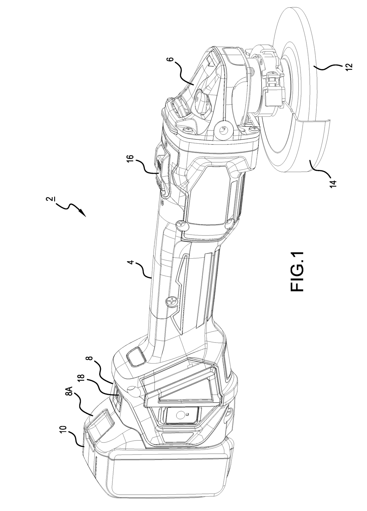
[0036]As shown in FIG. 1, grinders 2 of the embodiments described herein may principally comprise a motor housing 4, a gear housing 6, and a rear housing 8. The motor housing 4 has a circular-cylinder shape, which has an outer diameter (shell) that can be grasped by a user, and houses a motor 30 (refer to FIG. 3) in the interior thereof. The motor 30 is disposed inside the motor housing 4 such that a rotary shaft of the motor 30 is substantially parallel (or coincides) with the central longitudinal axis of the motor housing 4, and the rotary shaft of the motor 30 projects toward the gear housing 6.
[0037]The rear housing 8 is provided on one end of the central longitudinal axis of the motor housing 4 (more specifically, on the side of the motor housing 4 opposite the gear housing 6). In addition, a battery mounting part 8A is provided on a rear end of the rear housing 8 on the side opposite the motor housing 4. A rechargeable battery pack 10, i.e. a direct-current power supply, can b...
second embodiment
[0077]In the first embodiment, it was described that, if the slide switch 16 is turned OFF and thus a command to stop the motor 30 is input, then the braking control is performed and, under that braking control, the braking force generated in the motor 30 owing to the braking current flowing to the motor 30 is controlled (variably adjusted as needed in view of the rotational speed of the motor 30).
[0078]In contrast, in the second embodiment, when a command to stop the motor 30 is input, the flow of current to the motor 30 is first cut off without applying a braking force for a prescribed (predetermined) standby time, and then, after the standby time has elapsed, braking control is performed by applying the braking current to the motor 30 in a manner similar to the first embodiment.
[0079]Preferably, the braking force after the input of the stop command can be reduced or minimized by adjusting (increasing / decreasing) the standby time interval from the cut-off of the flow of current to...
modified example 1
[0096]In the above embodiments, it was described that, after a command to stop the motor 30 has been input to the controller 50, the braking force generated when the motor 30 is being stopped, including (optionally) the standby time, is set based on the set rotational speed when the motor 30 is started up.
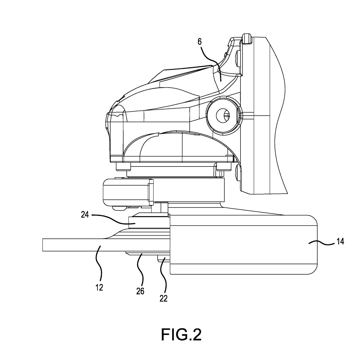
[0097]In the above embodiments, the acceleration of the motor 30 during startup (i.e. from standstill until the target rotational speed is reached) is either constant (or substantially constant) or follows a predetermined acceleration profile (pattern), such that the tightening force (torque) applied to the lock nut 26 during motor start up directly corresponds (is directly proportional) to the target rotational speed or to a lower rotational speed, in case the target rotational speed was not reached when the slide switch 16 was turned off. That is, because the amount of tightening force (torque) applied to the lock nut 26 corresponds to the amount of acceleration (more particularl...
PUM
 Abstract
Description
Claims
Application Information
 - R&D
- Intellectual Property
- Life Sciences
- Materials
- Tech Scout
- Unparalleled Data Quality
- Higher Quality Content
- 60% Fewer Hallucinations
Browse by: Latest US Patents, China's latest patents, Technical Efficacy Thesaurus, Application Domain, Technology Topic, Popular Technical Reports.
© 2025 PatSnap. All rights reserved.Legal|Privacy policy|Modern Slavery Act Transparency Statement|Sitemap|About US| Contact US: help@patsnap.com