Method for manufacturing a three-dimensional product

a three-dimensional product and manufacturing method technology, applied in additive manufacturing, mechanical equipment, additive manufacturing, etc., can solve the problems of frequent rework of constructions in a costly manner, fluid lines in the corresponding sizes and aspect ratios cannot be obtained by casting methods, and the design flexibility is severely restricted

Active Publication Date: 2019-03-21
ROBERT BOSCH GMBH
View PDF6 Cites 0 Cited by
  • Summary
  • Abstract
  • Description
  • Claims
  • Application Information

AI Technical Summary

Benefits of technology

[0006]The described method in particular makes it possible to route ducts in the product to be manufactured in an optimal manner from the aspect of fluid dynamics. Complex manufacturing steps such as deep drilling and / or an assembly including the sealing of complex add-on parts are not required. There is also no need to use a particularly complex core.
[0007]The product to be manufactured is able to be produced by a novel manufacturing method using the described method. This particularly allows for a related constructive redesign of the product to be manufactured.

Problems solved by technology

Afterwards, these constructions are regularly reworked in a costly manner in a machining operation.
Fluid lines in the corresponding sizes and aspect ratios can often not be obtained by casting methods.
Instead, it is often necessary to produce fluid lines after the fact using cost-intensive production methods such as deep drilling, for example.
In addition to the high manufacturing expense, the design flexibility is severely restricted by the conventional production process.
This often results in a restricted design flexibility and / or in additional required sealing points as a result thereof.
Another disadvantage of the conventional manufacture is the development of the ducts, which is less than optimal from the aspect of fluid dynamics.
Among other things, cavitation and pressure-loss problems as well as losses in the dynamic response during a valve actuation may be the consequence.
For instance, partially complex cores that require exact positioning are necessary.
However, the additive manufacturing process is usually much more complex than a casting process, for example, especially when a large volume of material must be applied.
Great geometrical complexity may be present especially when a manufacture by casting is impossible or possible only at a great expense (e.g., using complex cores that require precise positioning).
Great geometrical complexity is encountered in particular when the respective section includes ducts that have a complex shape and, in particular, have a small diameter and / or a great length.
More specifically, great geometrical complexity is present when a section includes ducts featuring a large aspect ratio (i.e. a ratio of length to diameter).
This means that the development of the product to be manufactured is preferably already realized in such a way that the subdivision into the first and the second section is particularly uncomplicated.
However, the third section may also have multiple subsections that are not cohesive.
For example, a part may not be suitable as a substrate for the additive manufacture if the at least one second connection surface is too small and / or too uneven.
Under these circumstances, it would not be practical to combine the two abutting parts that are not to be additively produced into a first section.
An additive manufacture between two surfaces that lie opposite each other, for example, is not possible or is possible only with great difficulty.
On the other hand, the additive construction of the oil filter receptacle would mean a considerable measure of material, support structure as well as build-up time and build-up costs.
In contrast to the components that are mounted as add-on parts on manufactured products according to the related art, the third section in particular may have a simple geometry that does not justify an additive construction on account of its low complexity.

Method used


Image

  • Method for manufacturing a three-dimensional product

Examples


Embodiment Construction

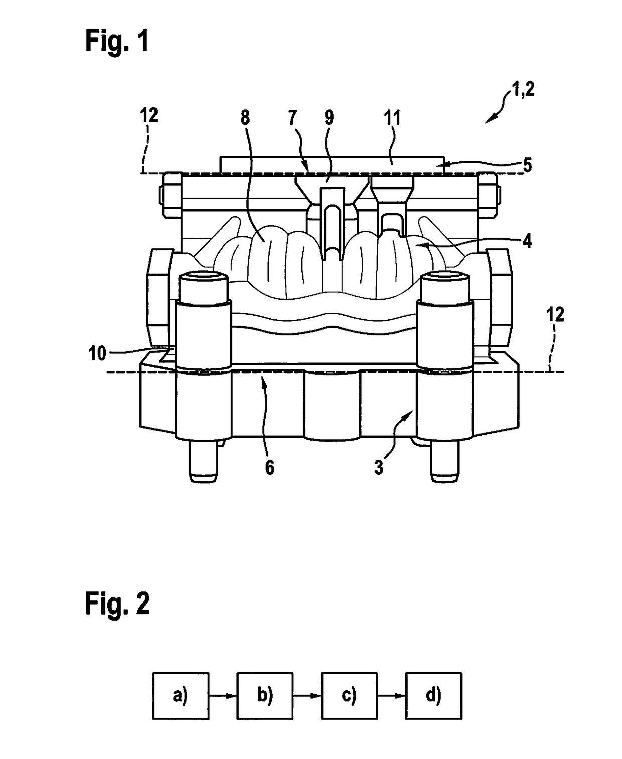
[0056]FIG. 1 shows a product 1 to be manufactured, which is a hydraulic element 2, in particular a servo directional control valve in a 4-directional embodiment. Product 1 has a first section 3, a second section 4, and a third section 5. First section 3 is produced by machining. First section 3 has a first connection point 6 via which first section 3 is connected to second section 4. Second section 4 is produced by an additive manufacturing process where first connection point 6 is used as the substrate. Second section 4 has a second connection point 7 via which second section 4 is connected to third section 5. Third section 5 is produced by machining and has then been connected to second connection surface 7. Second connection point 7 has a receptacle 9.

[0057]Second section 4 has a greater geometrical complexity than first section 3 and third section 5. This is particularly due to the fact that second section 5 includes a duct 8 for a fluid.

[0058]An advantageous selection of separa...


PUM

PropertyMeasurementUnit
sizesaaaaaaaaaa
aspect ratiosaaaaaaaaaa
aspect ratioaaaaaaaaaa

Abstract

A method is described for manufacturing a three-dimensional product, in particular a hydraulic element, the method encompassing at least the following method steps: Providing a first section of the product to be manufactured, which includes at least one first connection point for a second section of the product to be manufactured; and producing the second section by an additive manufacture in which the at least one first connection point of the first section is used as a substrate for the additive manufacture of the second section.

Description

BACKGROUND INFORMATION[0001]Hydraulic components such as servo directional control valves are normally produced as a cast construction. Afterwards, these constructions are regularly reworked in a costly manner in a machining operation. More specifically, it is often necessary to drill fine fluid lines into the cast components. Fluid lines in the corresponding sizes and aspect ratios can often not be obtained by casting methods. In this context, the aspect ratio is the ratio of the length of the fluid line to the diameter of the fluid line. Instead, it is often necessary to produce fluid lines after the fact using cost-intensive production methods such as deep drilling, for example.[0002]In addition to the high manufacturing expense, the design flexibility is severely restricted by the conventional production process. For example, the fluid conduits produced by the drilling methods can be reproduced only by bores that are cut in a straight line. This often results in a restricted des...

Claims


Application Information

Patent Timeline
Patent Type & Authority Applications(United States)
IPC IPC(8): B29C64/10B29C64/20
CPCB29C64/10B29C64/20B33Y80/00B33Y10/00B22F7/062B22F7/08B22F5/106B22F2999/00F15B13/04F15B2211/615F15B13/0817Y02P10/25B22F10/40B22F10/28F15B13/00
Inventor RAUCH, JOHANNESSEITZ, BENJAMINAMRHEIN, BERTRAMWILLECK, HANNESLOEBER, LUKASSCHOEPF, MARTIN
Owner ROBERT BOSCH GMBH
Why Eureka
Try Eureka