Linear positioner
a positioner and linear technology, applied in the field of linear positioners, can solve the problems of lack of portability, low practicability, and difficulty in adjusting the position of the linear positioner,
- Summary
- Abstract
- Description
- Claims
- Application Information
AI Technical Summary
Benefits of technology
Problems solved by technology
Method used
Image
Examples
example 1
m with Linear Positioner
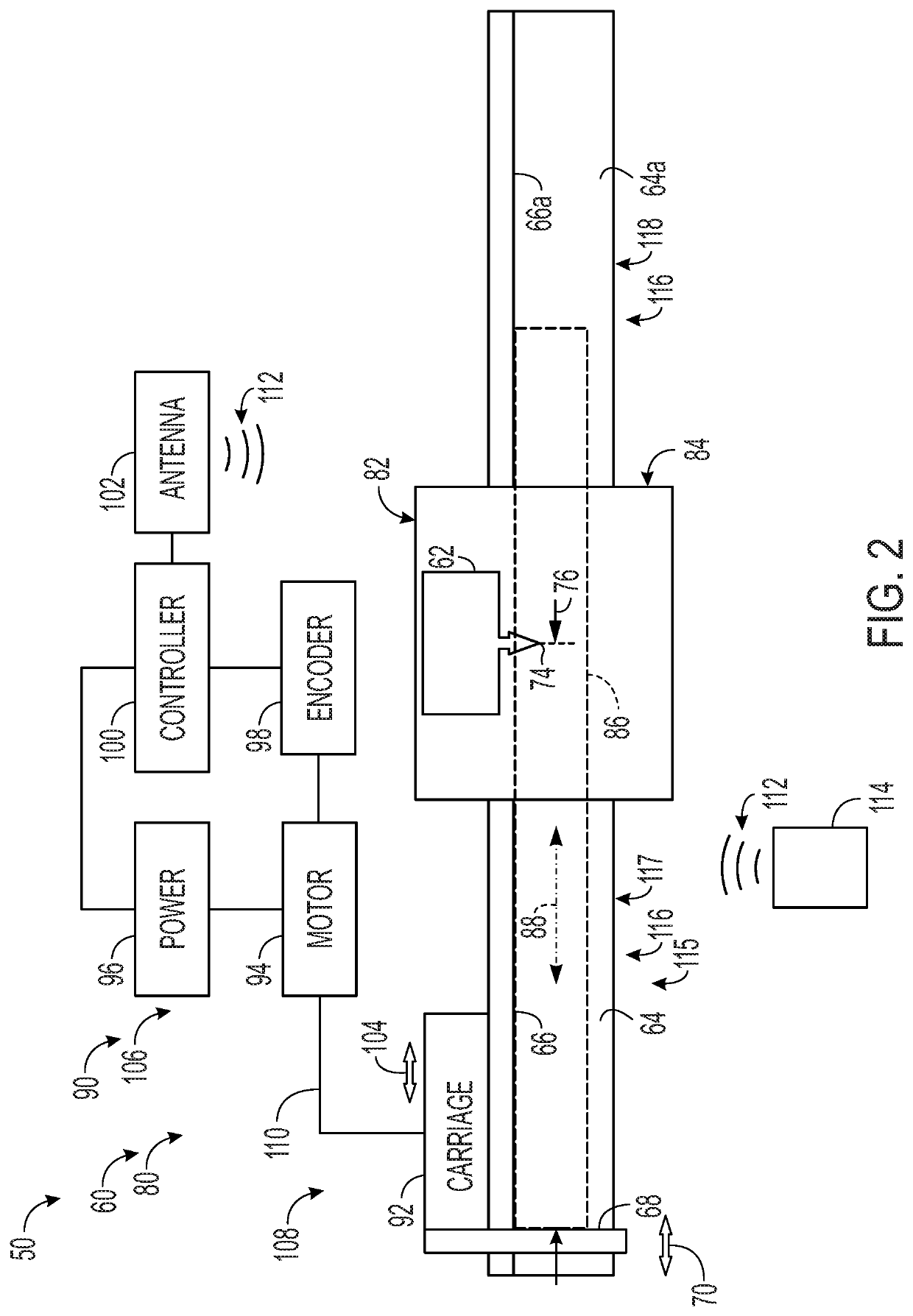
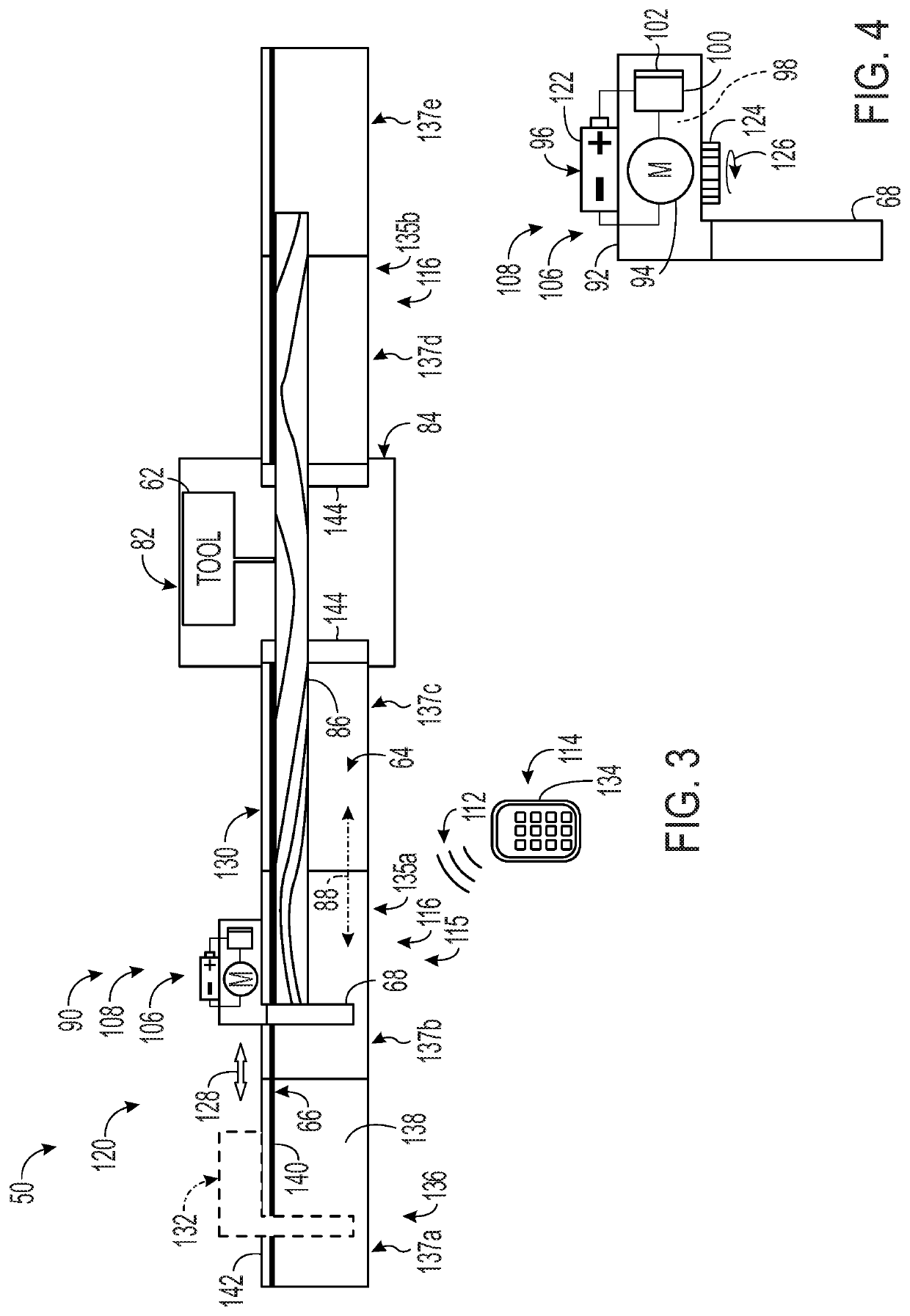
[0089]This section describes an exemplary workpiece-processing system 1050; see FIGS. 5-43 (also see FIGS. 2-4).
[0090]FIGS. 5 and 6 show workpiece-processing system 1050 having a linear positioner 1120 operatively connected to a miter saw 1146, which is supported by a stand 1084. The miter saw is a tool 1062 of a processing station 1082 of the workpiece-processing system.
[0091]Linear positioner 1120 is shown including a frame 1115 forming only one table 1116, namely, a segmented left worktable 1135 (compare with FIGS. 2 and 3). Worktable 1135 includes a deck 1064 to support a workpiece and contact an underside of the workpiece, a fence 1066 to orient the workpiece on deck 1064 by contact with a lateral side of the workpiece, and a track 1130. Each of deck 1064, fence 1066, and track 1130 is elongated parallel to the same axis, namely, the long axis of worktable 1135 (which is parallel to the measurement axis).
[0092]In the depicted embodiment, left worktable 1...
example 2
lip Coupling Mechanisms for Table Sections
[0119]This example describes exemplary mechanisms utilizing pins and clips to couple an adjacent pair of table sections of a linear positioner to one another; see FIGS. 44-47. The linear positioners of this example may have any suitable combination of the elements and features described elsewhere herein, such as for the linear positioners of Section I, Examples 1, 3, and 4 of Section II, and Section III.
[0120]FIGS. 44 and 45 show selected aspects of an exemplary linear positioner 2120, particularly, a top portion 2148 of a table section 2136 thereof. Top portion 2148 includes a deck member 2172 formed as an extrusion and then machined to create additional features, such as teeth 2270 of a rack segment 2273 and holes 2121. Deck member 2172 is generally like deck member 1172 of Example 1, except that deck member 2172 defines (a) integrally-formed clips 2123 to grip axial pins 2168 that align and couple adjacent table sections 2136 to one anoth...
example 3
Leg Assembly of a Table Section
[0125]This example describes an exemplary leg assembly 2156 for linear positioner 2120 that mounts to the underside of deck member 2172 of a table section 2136 in either a deployed configuration or a retracted, storage configuration; see FIGS. 48-51 (also see FIGS. 44 and 45 of Example 2 and compare with leg assembly 1156 of Example 1 (e.g., see FIGS. 26-30).
[0126]Leg assembly 2156 includes a fixed leg 2158a and a pivotable leg 2158b each connected to a bracket 2220 using fasteners 2145. Fixed leg 2158a has the same fixed position with respect to bracket 2220 in each configuration of leg assembly 2156. In contrast, pivotable leg 2158b is adjustable between a pivotable configuration and a fixed configuration. In the pivotable configuration, leg 2158b can pivot about an axis 2147 defined by one of fasteners 2145. This pivotability permits the orientation of pivotable leg 2158b to be changed relative to fixed leg 2158a, indicated by a rotation arrow 2149 ...
PUM
 Abstract
Description
Claims
Application Information
 - R&D
- Intellectual Property
- Life Sciences
- Materials
- Tech Scout
- Unparalleled Data Quality
- Higher Quality Content
- 60% Fewer Hallucinations
Browse by: Latest US Patents, China's latest patents, Technical Efficacy Thesaurus, Application Domain, Technology Topic, Popular Technical Reports.
© 2025 PatSnap. All rights reserved.Legal|Privacy policy|Modern Slavery Act Transparency Statement|Sitemap|About US| Contact US: help@patsnap.com


