
Autonomous cardiac implant of the leadless capsule type with energy harvester and controlled-charge energy storage buffer

a technology of leadless capsules and energy harvesters, which is applied in the direction of generators/motors, diagnostic recording/measuring, therapy, etc., can solve the problems of insufficient mechanical energy, low mechanical energy collection of the energy harvester, and complete exhaustion

Active Publication Date: 2019-03-28
CAIRDAC
View PDF8 Cites 15 Cited by
  • Summary
  • Abstract
  • Description
  • Claims
  • Application Information

AI Technical Summary

Benefits of technology

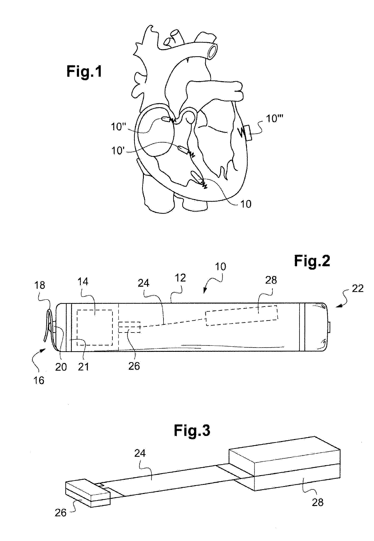
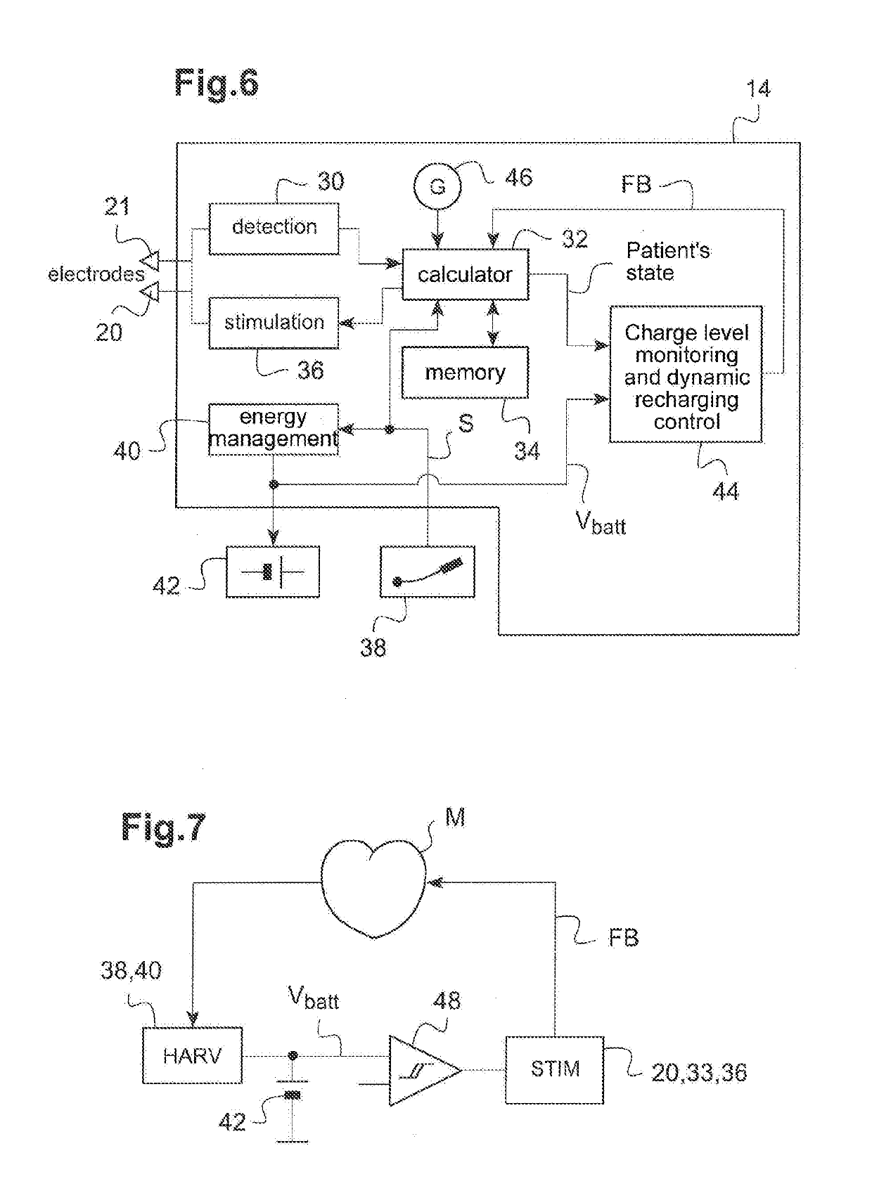
The invention is about a cardiac implant that can monitor its energy level and increase the mechanical energy produced by the heart's contractions to charge its energy storage component. This energy storage component then powers the implant and allows it to collect a higher energy level. The invention proposes an autonomous cardiac implant that includes an electronic unit, an energy storage component, a circuit for evaluating the energy level, a comparator, and an energy harvesting module. The electronic unit delivers stimulation pulses to the heart in a controlled manner based on the stimulation parameters. The energy harvesting module converts external stresses and cardiac tissue vibrations into electrical energy to power the electronic unit and / or charge the energy storage component. The dynamic charging control circuit modifies the stimulation parameters to increase the mechanical energy produced by the heart and power the electronic unit. The invention can be used in a leadless capsule type implant.

Problems solved by technology

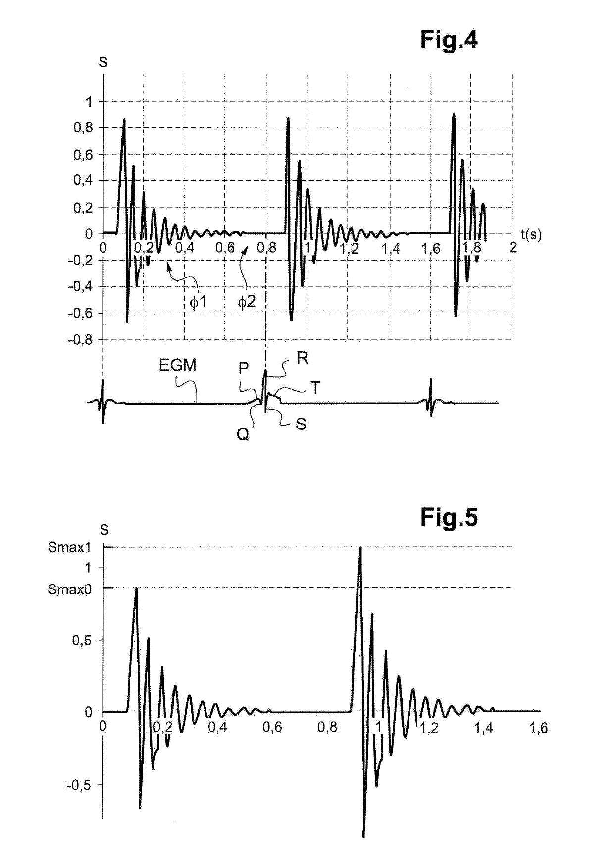
In particular, a reduced cardiac activity, characterized for example by a slow rhythm, bad hemodynamics causing a low blood flow rate, poor contractility of the myocardium with wall movements of low amplitude, etc., may lead to critical situations in which the electrical energy produced by the energy harvester would be insufficient to power the electronic circuit of the implant and, a fortiori, to charge the energy storage component that would progressively empty, risking a complete exhaustion.
The consumption of the electronic unit of the implant (electronic circuits, digital processors, sensors) may hence be relatively high in such situations in which, precisely, the mechanical energy collected by the energy harvester may be relatively low, or even insufficient.

Method used


Image

  • Autonomous cardiac implant of the leadless capsule type with energy harvester and controlled-charge energy storage buffer
  • Autonomous cardiac implant of the leadless capsule type with energy harvester and controlled-charge energy storage buffer
  • Autonomous cardiac implant of the leadless capsule type with energy harvester and controlled-charge energy storage buffer

Examples


Embodiment Construction

[0051]An exemplary embodiment of the device of the invention will now be described.

[0052]As regards its software aspects, the invention may be implemented by a suitable programming of the control software of a known cardiac stimulator device, for example a stimulator of the endocavitary leadless capsule type.

[0053]These devices include a programmable microprocessor or microcontroller coupled to circuits for receiving, shaping and processing electrical signals collected by electrodes arranged on the capsule, at least one of which is in contact with the myocardium, and delivering stimulation pulses to these electrodes. The adaptation of these devices to make the invention is within the reach of the one skilled in the art, and won't be described in detail. In particular, the software programs stored in memory and executed may be adapted or used to implement the functions of the invention that will be described hereinafter.

[0054]The method of the invention is indeed mainly implemented b...


PUM


Abstract

An energy harvester converts into electrical energy the external stresses applied to the implant at the heartbeat rhythm. This harvester comprises an inertial unit and a transducer delivering an electrical signal that is rectified and regulated for powering the implant and charging an energy storage component. The charge level of the energy storage component is compared with a lower threshold to detect an insufficient charge, and a dynamic charging control circuit modifies, as and whenever necessary, and if the current patient's state allows it, a stimulation parameter in a direction liable to increase in return the mean level of the mechanical energy that is produced and harvested.

Description

CROSS REFERENCE TO RELATED APPLICATIONS[0001]This application claims priority under 35 U.S.C. § 119(a) to French Patent Application Serial Number 1758769, filed Sep. 22, 2017, the entire teachings of which are incorporated herein by reference.BACKGROUND OF THE INVENTIONField of the Invention[0002]The invention relates to active implantable medical devices (AIMDs), in particular cardiac implants for monitoring the myocardium activity and delivering stimulation, resynchronization or defibrillation pulses in case of rhythm disorder detected by the device.Description of the Related Art[0003]The invention more particularly relates to those devices which incorporate a self-powering system including a mechanical energy harvesting device associated with an integrated energy storage component—it may be in particular a rechargeable battery or a high-performance capacitor. The harvesting device, also called harvester or scavenger, collects the mechanical energy resulting from the various movem...

Claims


Application Information

Patent Timeline
Patent Type & Authority Applications(United States)
IPC IPC(8): A61N1/378A61N1/39A61N1/365A61N1/375H10N30/88
CPCA61N1/3785A61N1/3975A61N1/36542A61N1/3756H01L41/053A61N1/37252H02N2/18A61B5/0422A61B5/287H10N30/88
Inventor BONNET, JEAN-LUC
Owner CAIRDAC
Learn More