Continuously operable mechanical or electrical power source fueled by gas or solid fuel including gas from improved biomass downdraft gasifier

a technology of gas or solid fuel and mechanical or electrical power source, which is applied in the direction of biofuels, coke ovens, combustible gas production, etc., can solve the problems of continuous operation and long-term operation for much more than

Active Publication Date: 2019-03-28
CHAGNOT CATHERINE J
View PDF1 Cites 1 Cited by
  • Summary
  • Abstract
  • Description
  • Claims
  • Application Information

AI Technical Summary

Benefits of technology

[0014]In one aspect, the invention is a downdraft gasifier that has a rotatable auger extending principally through the reduction zone of the gasifier working chamber. The upper end of the auger is positioned approximately between the combustion zone and the reduction zone and extends downward through the reduction zone. The auger serves two functions: (1) temporarily holding and periodically moving biofuel through the gasifier during its operation and (2) supporting biofuel in the gasifier in the manner of a grate. A frusto-conical biomass grate is arranged around the top of the auger for funneling biomass onto the auger. The frusto-conical biomass grate is perforated for permitting the passage of gases while retaining the biomass. A guide tube surrounds the auger and has an open upper end in registration with the narrower lower end of the frusto-conical biomass grate.

Problems solved by technology

However, despite that advantage, these gasifiers were commonly operated for only short periods of time because long term operation for much more than two hours was difficult due to the amount of tar and other pollutants in the fuel gas which would accumulate and disrupt proper operation of the engine.
Presently, long term, continuous operation remains a problem because gasifier operation must be halted periodically due to the formation of tar.
Another problem with current downdraft gasifiers is that they require a closure or lid at the top of the fire tube in order to limit the incoming air because the air flow through the fire tube is downward which is opposite the direction of air flow through the fire tube that would be expected from simple convection.
However, such an outlet passageway still requires a closure at the top of the fire tube that must be removed from time to time to refill biomass into the fire tube.

Method used


Image

  • Continuously operable mechanical or electrical power source fueled by gas or solid fuel including gas from improved biomass downdraft gasifier
  • Continuously operable mechanical or electrical power source fueled by gas or solid fuel including gas from improved biomass downdraft gasifier
  • Continuously operable mechanical or electrical power source fueled by gas or solid fuel including gas from improved biomass downdraft gasifier

Examples


Embodiment Construction

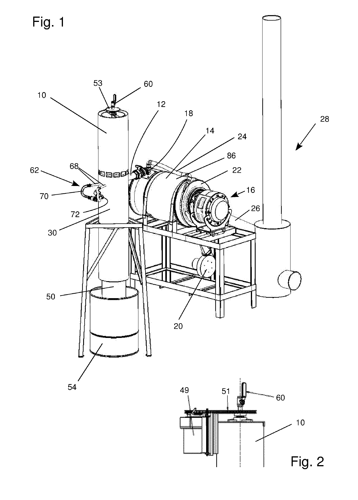
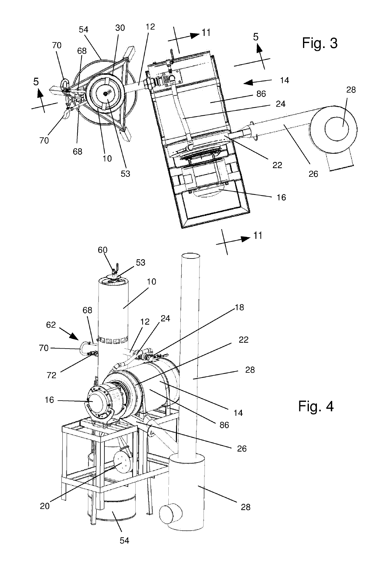
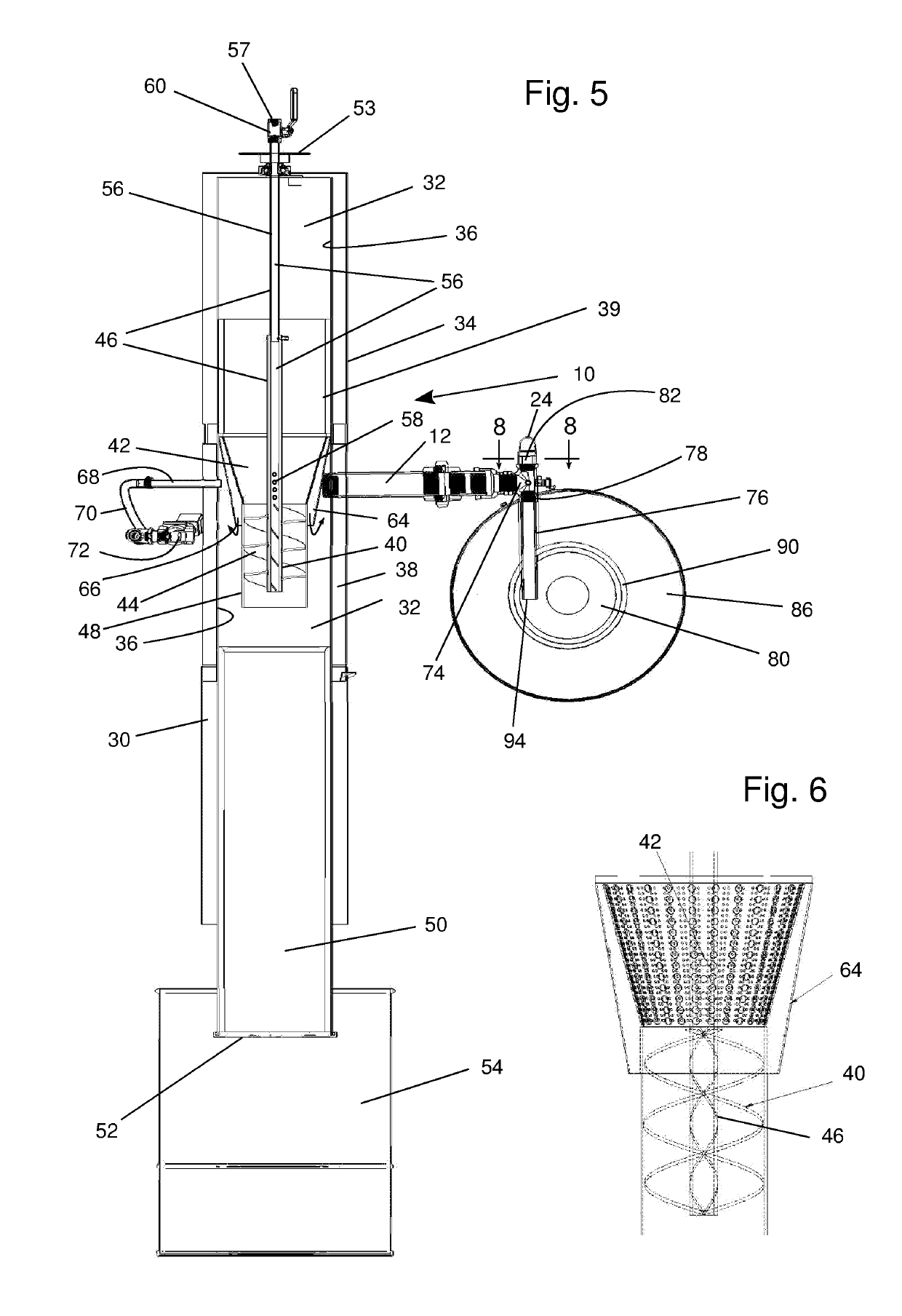
[0030]FIGS. 1 through 4 illustrate an overview of an assembled biomass-fueled power source that incorporates an embodiment of the invention. The main components are a downdraft gasifier 10 having a fuel gas outlet that is connected through a fuel gas outlet conduit 12 to the combustion chamber of a burner 14 that applies heat to a free-piston Stirling engine 16. The fuel gas outlet conduit 12 has an outer layer of insulation to help maintain the hot temperature of incoming gases so that tar compounds will not condense on the interior walls of the outlet conduit 12. That prevents the build-up of a layer of tar that would reduce and eventually block passage of fuel gas through the fuel gas outlet conduit 12. The engine 16 provides mechanical power to an internally and integrally mounted alternator for generating electrical power. Stirling engines of this and other types are well known in the prior art and are commercially available. Some examples of external combustion engines that ma...


PUM

PropertyMeasurementUnit
temperaturesaaaaaaaaaa
temperatureaaaaaaaaaa
pressureaaaaaaaaaa

Abstract

The invention includes a downdraft gasifier having a rotatable auger/grate extending through its reduction zone. The auger at times moves biofuel through the gasifier and at times supports it in the gasifier. A frusto-conical biomass grate funnels biomass onto the auger and is perforate for permitting the passage of gases while retaining the biomass. A guide tube surrounds the auger below the frusto-conical biomass grate. The invention also includes mixing gas or solid particulate fuel in a conduit segment that houses a mixing chamber. Fuel is fed through a fuel inlet port into the mixing chamber. High velocity combustion air from a blower is forced into the mixing chamber through a restricted orifice that generates a suction pressure for drawing gas or solid particulate fuel into the mixing chamber. A combustion chamber supply conduit delivers fuel from the mixing chamber into a burner.

Description

BACKGROUND OF THE INVENTION[0001]This invention relates to improvements in downdraft gasifiers and to improvements in burners that heat external combustion engines using gas or solid particulate fuel. The invention more specifically relates to power generation equipment that combines a mechanical power source in the form of an external combustion engine, such as a free-piston Stirling engine, with a downdraft gasifier that supplies fuel gas from multiple forms of biomass to a burner for powering an external combustion engine.[0002]There has long been a need for relatively small power generation equipment that can generate power for operating mechanical devices, such as water pumps or electrical devices like lighting and electrical motors, using locally available fuels as energy sources. One of the most promising options is an external combustion engine which is heated by fuel gas produced from biomass, such as dried manure, or dried vegetation in the form of sawdust, rice husks, cor...

Claims


Application Information

Patent Timeline
Patent Type & Authority Applications(United States)
IPC IPC(8): C10J3/34C10J3/22C10B53/02
CPCC10J3/34C10J3/22C10B53/02C10J2200/158C10J2300/0906C10J2300/0916C10J2300/0956C10J3/26C10J3/32C10J3/42C10J2200/36Y02E50/10
Inventor CHAGNOT, CATHERINE J.
Owner CHAGNOT CATHERINE J
Why Eureka
Try Eureka