
Conductive fiber comprising metal nanobelt and carbon nanomaterial composite, method for producing conductive fiber, fibrous strain sensor, and method for producing fibrous strain sensor

a technology of carbon nanomaterials and conductive fibers, which is applied in the direction of non-conductive materials with dispersed conductive materials, chemistry apparatuses and processes, and materials nanotechnology. it can solve the problems of difficult mass production, difficult to realize high conductivity of 10sup>5 /sup>s/m or more using only carbon nanomaterials, and achieve superior dispersion uniformity, increase the conductivity of conductive fibers, and improve the effect of resistan

Active Publication Date: 2019-03-28
KOREA ELECTROTECH RES INST
View PDF10 Cites 8 Cited by
  • Summary
  • Abstract
  • Description
  • Claims
  • Application Information

AI Technical Summary

Benefits of technology

The present invention provides a conductive fiber made of a metal-nanobelt-carbon-nanomaterial composite that increases the conductivity of the fiber and exhibits good contact between the carbon nanomaterial and the metal nanobelts. This results from the formation of the metal nanobelts on the surface of the carbon nanomaterial and superior dispersion uniformity. The conductive fiber can be used in fibrous strain sensors and works by enabling area contact between metal nanobelts. The fiber's high conductivity makes it effective for strain sensors that detect changes in resistance caused by tensile strain.

Problems solved by technology

Such a dry process facilitates high conductivity but makes it difficult to realize mass production.
However, the wet process is problematic in that the formation of a composite with a heterogeneous material such as a polymer, etc. is difficult.
However, it is difficult to realize high conductivity of 105 S / m or more using only the carbon nanomaterial.
Added to the carbon nanomaterial, however, metal nanoparticles undergo point contact, and metal nanorods, metal nanowires, metal nanotubes and metal nanoflakes undergo line contact, and thus limitations are imposed on increasing conductivity.
Furthermore, in the case where a conductive fiber is manufactured by individually adding a carbon nanomaterial and a metal material, the carbon nanomaterial and the metal material are not uniformly dispersed, and thus an additional dispersant has to be used.
Specifically, the case where the conventional material is applied to a strain sensor is problematic in that the conventional strain sensor cannot be applied to fields in which micro-strain may be detected because the resistance is not changed much even when the tensile strain is large.

Method used


Image

  • Conductive fiber comprising metal nanobelt and carbon nanomaterial composite, method for producing conductive fiber, fibrous strain sensor, and method for producing fibrous strain sensor
  • Conductive fiber comprising metal nanobelt and carbon nanomaterial composite, method for producing conductive fiber, fibrous strain sensor, and method for producing fibrous strain sensor
  • Conductive fiber comprising metal nanobelt and carbon nanomaterial composite, method for producing conductive fiber, fibrous strain sensor, and method for producing fibrous strain sensor

Examples


Embodiment Construction

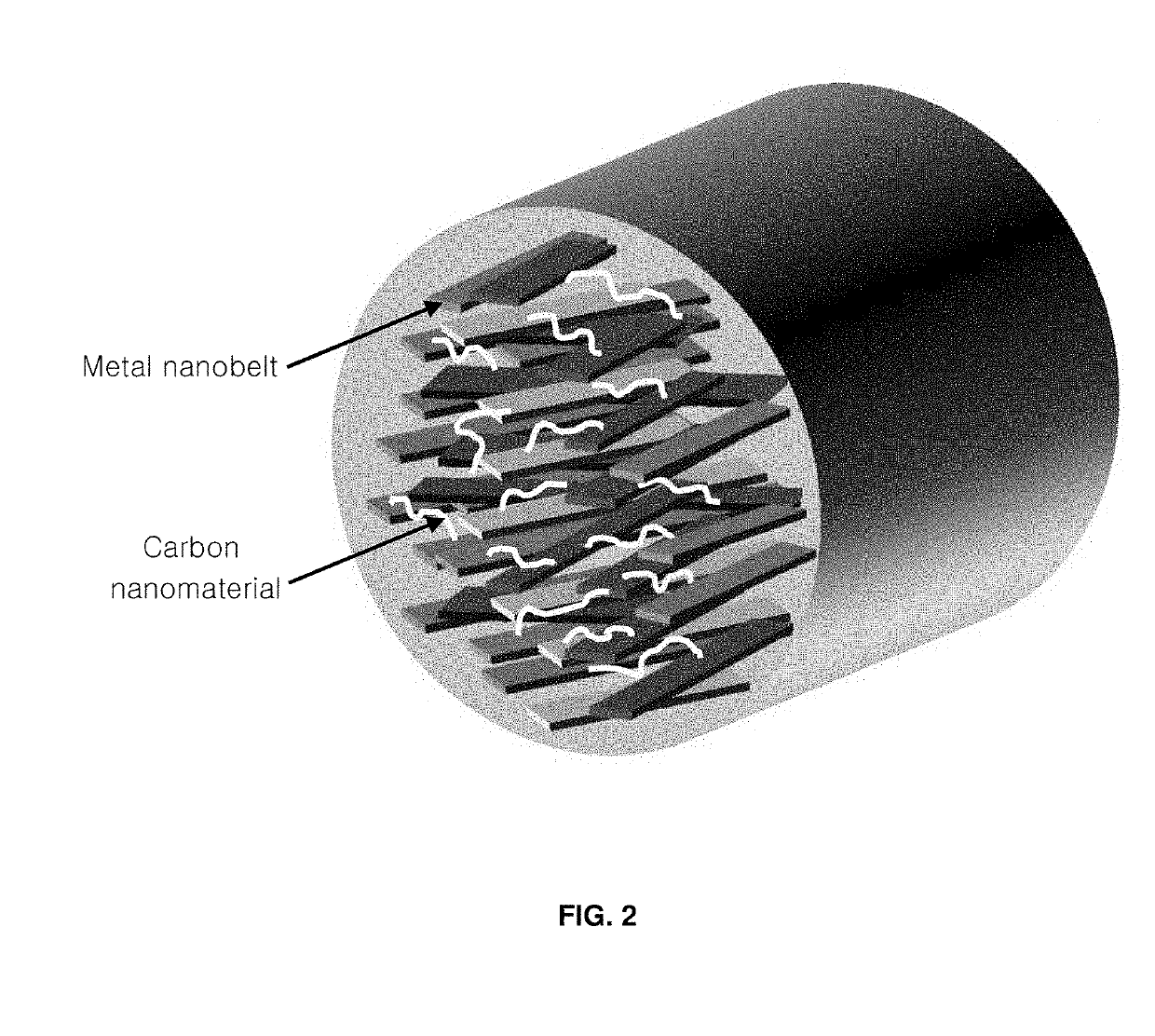
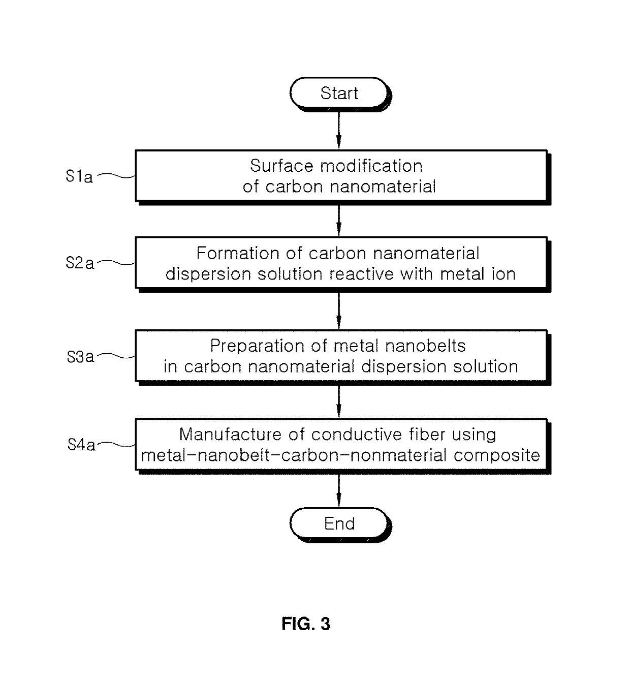
[0045]Hereinafter, a detailed description will be given of a conductive fiber comprising a metal-nanobelt-carbon-nanomaterial composite, a method of manufacturing the conductive fiber, a fibrous strain sensor and a method of manufacturing the fibrous strain sensor according to embodiments of the present invention. Here, the term “metal nanobelt” refers to one having a ribbon shape so as to enable area contact. The conductive fiber is preferably manufactured in a manner in which a surface-modified carbon nanomaterial is mixed and reacted with an isocyanate-based compound and a pyrimidine-based compound to yield a carbon nanomaterial dispersion solution reactive with metal ions, and a metal salt precursor and a solvent are added to the carbon nanomaterial dispersion solution and a reducing agent is added at a controlled addition rate to thus form the metal nanobelts on the surface of the carbon nanomaterial, after which the resulting carbon-nanomaterial-metal-nanobelt composite is mix...


PUM

PropertyMeasurementUnit
tensile strainaaaaaaaaaa
conductivityaaaaaaaaaa
electrical conductivityaaaaaaaaaa

Abstract

A conductive fiber including a metal-nanobelt-carbon-nanomaterial composite. A manufacturing method thereof includes preparing a composite including a carbon nanomaterial and metal nanobelts and manufacturing a conductive fiber by mixing the composite with a polymer. A fibrous strain sensor and a manufacturing method thereof are also provided. Thereby, a conductive fiber including a metal-nanobelt-carbon-nanomaterial composite, which is able to increase conductivity of the conductive fiber through synthesis of metal nanobelts enabling area contact and to exhibit good contact between the carbon nanomaterial and the metal nanobelts due to formation of the metal nanobelts on the surface of the carbon nanomaterial and superior dispersion uniformity, and a fibrous strain sensor including the conductive fiber can be obtained. The conductive fiber can be effectively applied to a strain sensor based on a principle by which resistance drastically increases with an increase in a distance between metal nanobelts aligned in a fiber direction upon tensile strain of metal nanobelts enabling area contact.

Description

REFERENCE TO RELATED APPLICATIONS[0001]This is a continuation of pending International Patent Application PCT / KR2017 / 005602 filed on May 30, 2017, which designates the United States and claims priority of Korean Patent Application No. 10-2016-0068255 filed on Jun. 1, 2016, the entire contents of which are incorporated herein by reference.FIELD OF THE INVENTION[0002]The present invention relates to a conductive fiber comprising a metal-nanobelt-carbon-nanomaterial composite, a method of manufacturing the conductive fiber, a fibrous strain sensor, and a method of manufacturing the fibrous strain sensor. More particularly, the present invention relates to a conductive fiber comprising a metal-nanobelt-carbon-nanomaterial composite, which is able to increase conductivity through synthesis of metal nanobelts enabling area contact and to exhibit good contact between the carbon nanomaterial and the metal nanobelts due to formation of the metal nanobelts on the surface of the carbon nanomat...

Claims


Application Information

Patent Timeline
Patent Type & Authority Applications(United States)
IPC IPC(8): G01B7/16C08K3/04C08K3/08C08K7/00C01B32/168C01B32/194C08J3/21D01F1/09D01F8/10D01F8/18D01F9/12D01F8/16H01B1/22H01B1/24
CPCG01B7/18C01B2204/22C08K3/08C08K7/00D10B2101/20D10B2321/06D10B2331/10C08K3/041C01B32/168C01B32/194C08J3/212D01F1/09D01F8/10D01F8/18D01F9/12D01F8/16H01B1/22H01B1/24B82Y15/00B82Y40/00C08K2201/001C08K2201/011C08K2003/0806C08K2003/0843C01B2202/22C01B2202/06D10B2401/16C08J2329/04C01B32/174B82Y30/00D01F8/04C01B32/15
Inventor HAN, JOONG TARKLEE, GEON WOONGSEO, SEON HEEJANG, JEONG INJEONG, SEUNG YOLJEONG, HEE JIN
Owner KOREA ELECTROTECH RES INST
Learn More