
Driving assistance control device

a technology of driving assistance and control device, which is applied in the direction of automatic initiation, transportation and packaging, propulsion unit arrangement, etc., can solve the problems of conflict of intention between human and machine, inability to achieve the preferred degree of deceleration, and difficulty for the driver (human) to understand

Active Publication Date: 2019-04-11
TOYOTA JIDOSHA KK +3
View PDF3 Cites 21 Cited by
  • Summary
  • Abstract
  • Description
  • Claims
  • Application Information

AI Technical Summary

Benefits of technology

The patent describes a system for assisting drivers in controlling their vehicles to avoid collisions and accidents. The system uses sensors and data from the vehicle's surroundings to detect potential risks and issue warnings to the driver. The driver can then decide to decelerate or accelerate to avoid the risk. The system integrates the driver's manipulation of the accelerator or brakes into the driving experience, making it easier for them to control the vehicle's speed. The system can also adjust the assistance reaction force based on the driver's speed to provide better control and stability. Overall, the system improves safety and driver control.

Problems solved by technology

Therefore, when an obstacle suddenly rushes from the blind spot area (viewed from the subject vehicle) such as behind a parked vehicle, a shade, or an intersection with poor visibility or when the obstacle traveling beside the road suddenly enters the road, a preferred degree of deceleration may not be achieved.
However, in reality, when a blind spot area or an obstacle beside the road is found, the obstacle does not always rush into the road, and constant execution of deceleration of the vehicle on the assumption of a worst case scenario for an uncertain case as described above may not match an intention of a driver of the vehicle since the driver may have various motives in driving.
For example, when the system (machine) recognizes the blind spot area or the obstacle beside the road and predicts the potential risk, and the driver (human) can apparently determine that the obstacle will not rush, a conflict of intention between the human and the machine occurs.
In this case, even though the deceleration operation by the system (machine) is preferable, it is difficult for the driver (human) to understand the control intention, or when a driving intention of the driver is not reflected at all in the control operation of the system, the driver is likely to feel uncomfortable with respect to the control operation of the system.
When the “potential risk area” is detected during traveling of the vehicle, a potential risk of an obstacle rushing out of the potential risk area is predicted.
Further, since the driver receives a force in a direction in which the amount of manipulation of the active pedal is reduced, it is difficult to increase the amount of manipulation of the active pedal, thereby preventing the vehicle speed from being easily accelerated.
However, when the application of the assistance reaction force is stopped before the vehicle speed falls below the reference speed, a sudden change in the force acting on the active pedal can occur.

Method used


Image

  • Driving assistance control device
  • Driving assistance control device
  • Driving assistance control device

Examples


Embodiment Construction

[0035]Configuration of Vehicle

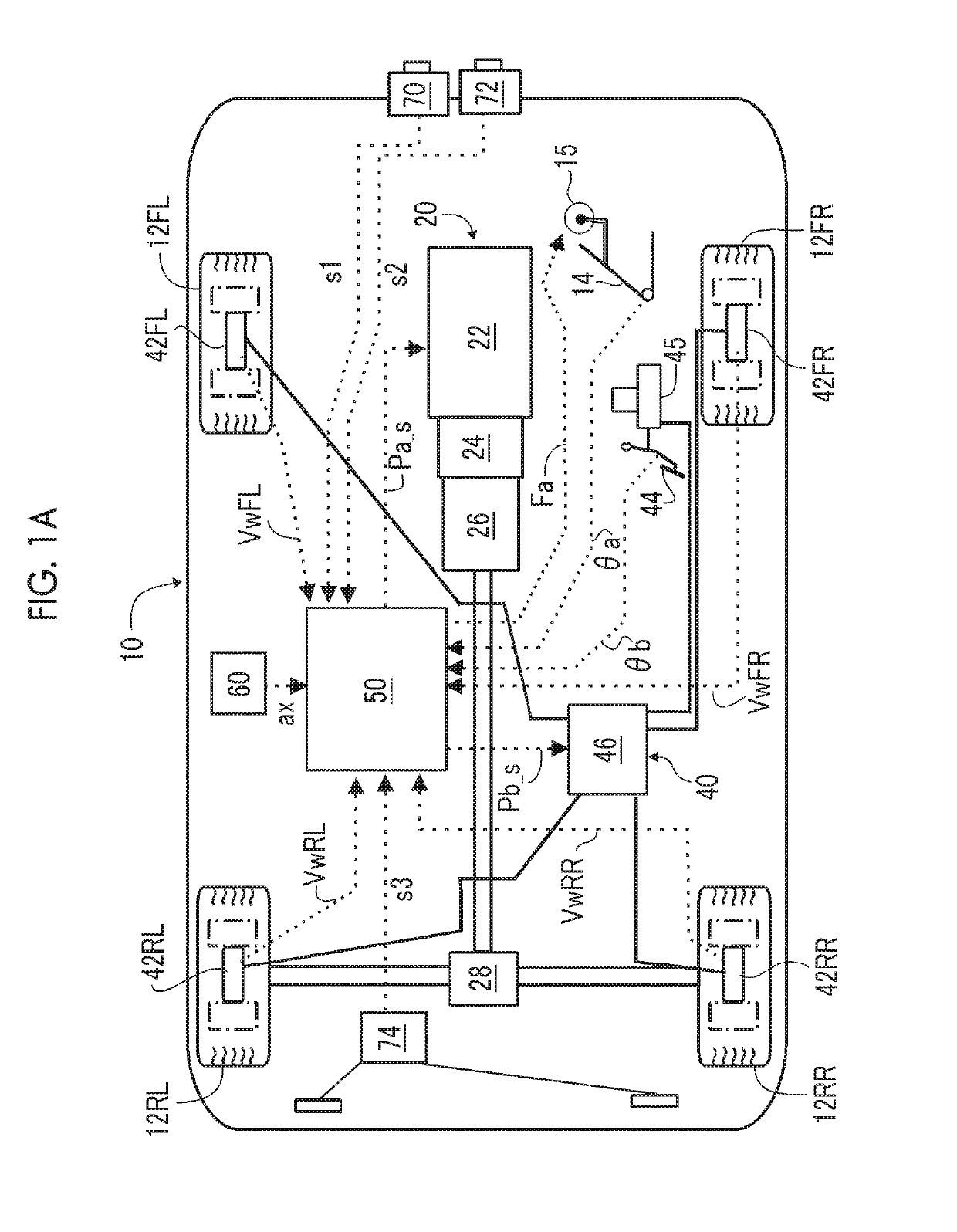
[0036]Referring to FIG. 1A, in a vehicle 10 such as a car in which a preferred embodiment of a driving assistance control device of the present disclosure is incorporated, right and left front wheels 12FR, 12FL, right and left rear wheels 12RR, 12RL, a driving device 20 that generates a braking and driving force for each wheel (in the illustrated example, solely a rear wheel since a vehicle is a rear wheel driven vehicle in the illustrated example), a steering device (not illustrated) for controlling a steering angle of vehicle wheels, and a brake device 40 that generates a braking force for each wheel are mounted in a normal aspect. The driving device 20 is configured such that a driving torque or a rotational force is transmitted from an engine and / or an electric motor 22 (which may be a hybrid driving device including both the engine and the electric motor) to rear wheels 12RL, 12RR via a torque converter 24, a transmission 26, a differential gear de...


PUM


Abstract

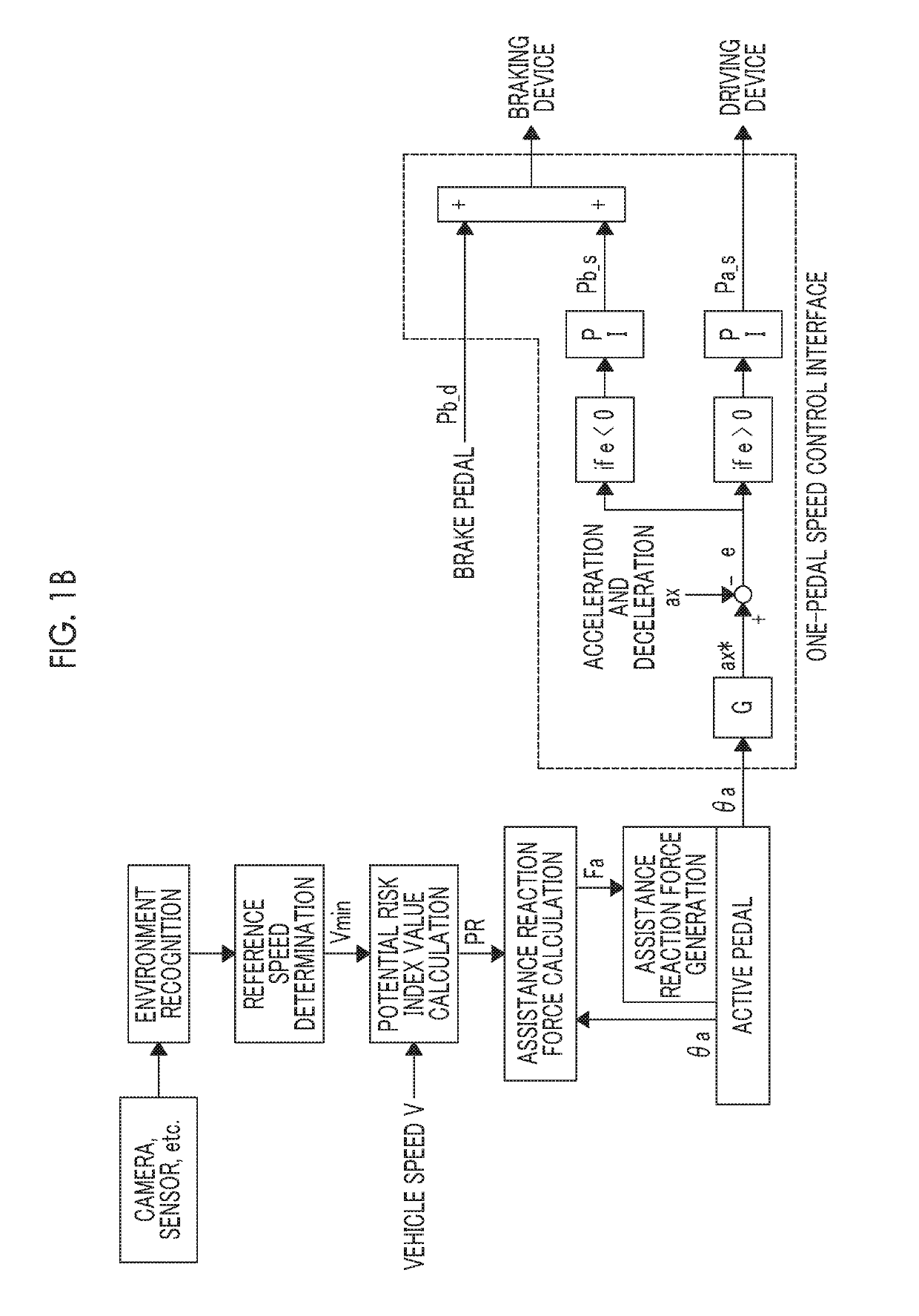
A driving assistance control device includes an active pedal configured to control a driving and braking force of a vehicle, an electronic control unit configured to detect a potential risk area in which an obstacle entering a scheduled traveling route of the vehicle is likely to be present, and determine a reference speed at which contact between the vehicle and the obstacle can be avoided even when the obstacle enters the scheduled traveling route of the vehicle from the detected potential risk area based on a positional relationship between the vehicle and the potential risk area, and a force feedback unit configured to apply an assistance reaction force in a direction in which the amount of manipulation is reduced, to the active pedal when a current speed of the vehicle exceeds the reference speed.

Description

INCORPORATION BY REFERENCE[0001]The disclosure of Japanese Patent Application No. 2017-195282 filed on Oct. 5, 2017 including the specification, drawings and abstract is incorporated herein by reference in its entirety.BACKGROUND1. Technical Field[0002]The present disclosure relates to a device for assisting in driving of a vehicle such as a car, and more particularly, to a device that executes driving assistance for achieving avoidance of contact with a pedestrian or a bicycle (an obstacle) that rushes into or enters a scheduled traveling route in front of a vehicle from a blind spot area or an area beside a road, which is a blind spot for a driver such as a shadow of an obstacle beside the road or a building, or reduction in impact at the time of contact during traveling of the vehicle.2. Description of Related Art[0003]As a vehicle driving assistance system, a configuration for avoiding collision or contact with an obstacle detected in a traveling direction of a traveling vehicle...

Claims


Application Information

Patent Timeline
IPC IPC(8): B60W30/09B60T7/12
CPCB60W30/09B60T7/12B60W2520/10B60W2550/10B60W2710/182B60W50/16B60W30/095B60W2720/10B60W30/0953B60W30/0956B60K31/02B60K31/0008B60K26/021B60K2026/023B60W2554/00B60W2554/801
Inventor INOUE, SHINTARORAKSINCHAROENSAK, PONGSATHORNSAITO, YUICHIITO, TAKUMASHIMIZU, TSUKASAINOUE, HIDEO
Owner TOYOTA JIDOSHA KK
Learn More