Exhaust system

a technology of exhaust gas and components, applied in the direction of mechanical equipment, machines/engines, transportation and packaging, etc., can solve the problems of unwanted deposits on the surface of components, and achieve the effect of reducing the risk of deposits on exhaust gas-carrying components

Active Publication Date: 2019-04-11
PUREM GMBH
View PDF12 Cites 1 Cited by
  • Summary
  • Abstract
  • Description
  • Claims
  • Application Information

AI Technical Summary

Benefits of technology

[0004]An object of the present invention is to provide an exhaust system, in which the risk of formation of deposits on exhaust gas-carrying components is reduced.

Problems solved by technology

Especially in case of adverse thermal conditions, i.e., for example, at low ambient temperatures or low exhaust gas temperatures, or / and high dispensing rates for the reactant, there is the risk that this decomposition proceeds incompletely or with the formation of intermediate products, which may lead to the formation of unwanted deposits on surfaces of the components carrying the exhaust gas or the reactant.

Method used


Image

  • Exhaust system
  • Exhaust system
  • Exhaust system

Examples


Embodiment Construction

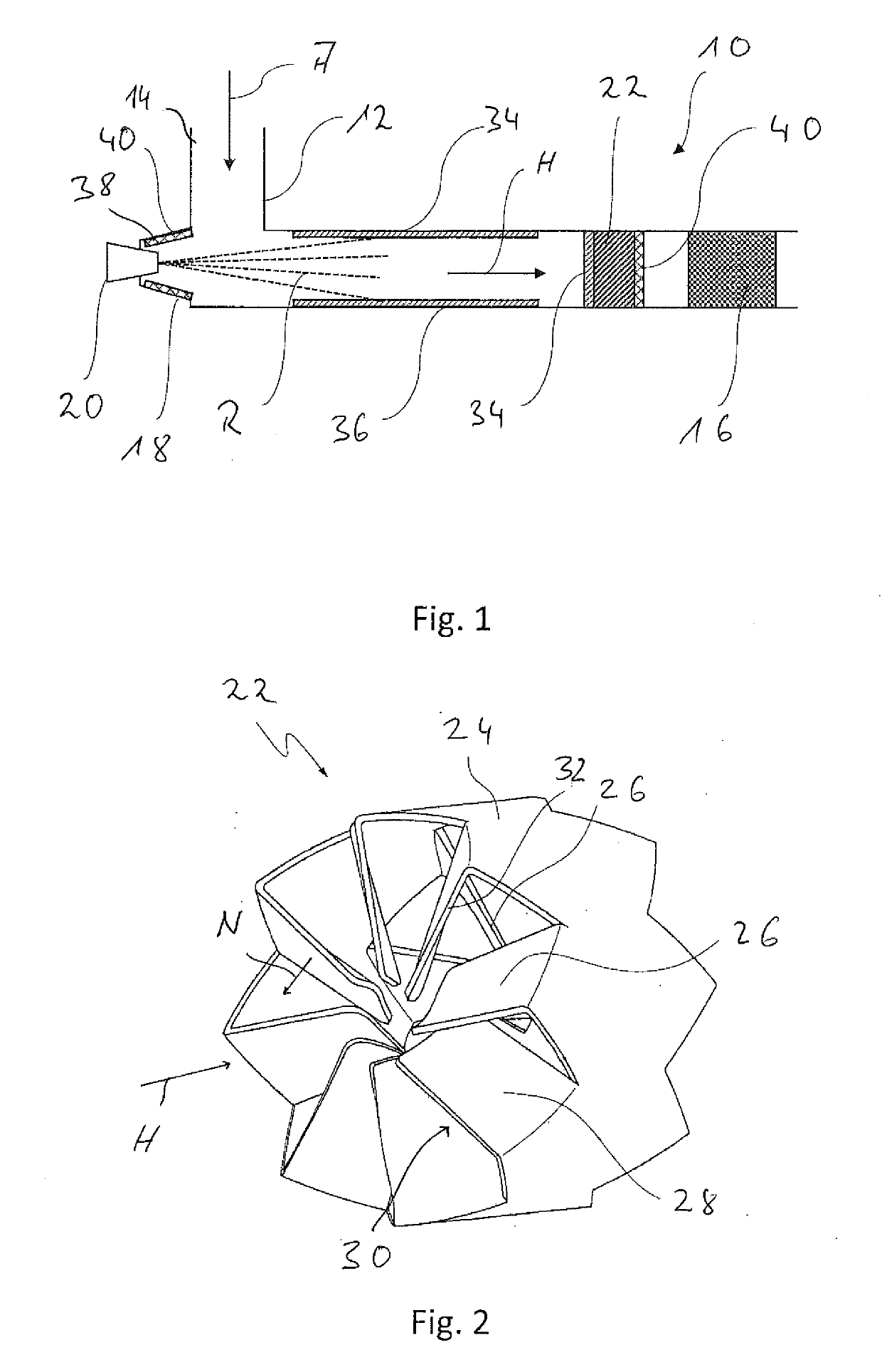
[0025]Referring to the drawings, FIG. 1 shows a part of an exhaust system, generally designated by 10, of an internal combustion engine. The exhaust gas A emitted from an internal combustion engine flows in an exhaust gas duct 14 provided in a pipe 12 in the direction towards a catalytic converter device 16, for example, an SCR catalytic converter device. The pipe 12 may consist of one part or may be composed of a plurality of parts. In the pipe 12 the exhaust gas A flows along an exhaust gas main flow direction H, which may essentially also correspond to the direction of longitudinal extension of the pipe 12 in a corresponding pipe section, which may possibly also have a curved configuration.

[0026]A reactant release device 20, which is also generally called injector, is provided in the area of a reactant release pipe connection 18 provided at the pipe 12. The reactant release device 20 releases a reactant R in the form of a spray cone into the exhaust gas flow duct 14, i.e., into t...


PUM

PropertyMeasurementUnit
angleaaaaaaaaaa
critical angleaaaaaaaaaa

Abstract

An exhaust system for an internal combustion engine, especially in a vehicle, includes an exhaust gas flow duct (14), a reactant release device (20) for the release of reactant (R) into the exhaust gas flow duct (14) and a catalytic converter device (16) downstream of the reactant release device (20). At least one part of a component surface is provided by a hydrophilic material (34) of at least one exhaust gas-carrying component (12, 22) positioned in the reactant flow path or/and defining this reactant flow path, or/and at least one part of the component surface is provided by a hydrophobic material (40) of at least one exhaust gas-carrying component (12, 18, 22) positioned in the reactant flow path.

Description

CROSS REFERENCE TO RELATED APPLICATIONS[0001]This application claims the benefit of priority under 35 U.S.C. § 119 of German Application 10 2017 123 447.0, filed Oct. 10, 2017, the entire contents of which are incorporated herein by reference.TECHNICAL FIELD[0002]The present invention pertains to an exhaust system for an internal combustion engine which can be used, for example, in a vehicle, to release exhaust gas emitted from an internal combustion engine into the environment.BACKGROUND[0003]In order to reduce the pollutant content of exhaust gas emitted from an internal combustion engine, especially a diesel internal combustion engine, it is known to add a reactant, for example, a urea / water solution, to the exhaust gas, in order to reduce the nitrogen oxide content in the exhaust gas in a selective catalytic reduction carried out in a catalytic converter device. The reactant fed to the exhaust gas is decomposed before carrying out the selective catalytic reduction, especially in...

Claims


Application Information

Patent Timeline
Patent Type & Authority Applications(United States)
IPC IPC(8): F01N3/28F01N3/20B01F3/04B01F5/06
CPCF01N3/2892F01N3/2066B01F3/04049B01F5/061F01N2610/02F01N2610/1453F01N2240/20B01F2005/0639F01N3/28F01N13/00F01N13/16F01N2510/00Y02A50/20Y02T10/12B01F23/2132B01F25/431B01F25/431974B01F25/4315
Inventor GAISER, GERDWELLER, BERND
Owner PUREM GMBH
Why Eureka
Try Eureka