Stereoscopic three dimensional projection system with short throw ratio

a three-dimensional projection and short throw ratio technology, applied in the field of stereoscopic three-dimensional projection systems with short throw ratios, can solve the problems of reducing the overall optical light efficiency of said single image, reducing the size of optical components, and reducing the brightness of on-screen stereoscopic 3d images, etc., to achieve the effect of improving image quality and on-screen homogeneity, and short throw ratios

Active Publication Date: 2019-04-11
VOLFONI R&D EURL
View PDF0 Cites 1 Cited by
  • Summary
  • Abstract
  • Description
  • Claims
  • Application Information

AI Technical Summary

Benefits of technology

[0023]An object of the present invention is to provide a time-multiplexed stereoscopic 3d projection system that is capable of operating together with a projector having a shorter throw-ratio as compared to other prior-art technologies. A further object of the present invention is to provide a stereoscopic 3d image with improved image quality and on-screen homogeneity when used together with a laser projector.
[0024]The invention is based on the insight that in order to be able to operate together with a projector having a short throw-ratio, the optical path-lengths for image-beams passing through said stereoscopic 3d system are mandated to be minimized in order to ensure the sizes of optical components composing said stereoscopic 3d system are kept below practical limitations. Furthermore, in order to improve the optical clarity and on-screen homogeneity when using a laser projector, it is mandated to minimize the occurrence of optical diffraction and other related defects at the centre of any beam-splitting element used in said stereoscopic 3d system thereof.
[0025]Moreover, the present invention is further based on the insight that in order to fulfill the requirement of minimizing the optical path-lengths for said image-beams passing through said stereoscopic 3d projection system, it is principally the angular beam divergence in the vertical direction that determines the overall optical path-lengths and not the angular beam divergence in the horizontal direction. This therefore enables a uniaxial condensing lens to be used according to the present invention in order to first reduce the divergence of the incident image-beam in the vertical direction whilst leaving the divergence angle of said incident image-beam in the horizontal direction substantially unperturbed, thereby enabling the optical path-lengths for said image-beams to be significantly reduced. Thereafter, a uniaxial expanding lens is then used to expand the divergent angle in the vertical direction back to its original value for said image-beams exiting said stereoscopic 3d system thereof, hence enabling said stereoscopic 3d projection system according to the present invention to provide for a shorter throw-ratio as compared to other prior-art technologies.
[0026]Moreover, a further preferred embodiment of the present invention is that a double image-beam architecture is preferentially used where the beam-splitting element comprises a single plane or plate, thereby mitigating the occurrence of optical diffraction and other related defects at the surface of said single plate thereof. This provides for a stereoscopic 3d projection system according to the present invention that generates an improved level of optical clarity and on-screen homogeneity when used together with a laser projector.

Problems solved by technology

However, since the images generated by a typical 3-chip DLP digital cinema projector are initially randomly polarized (i.e unpolarized), then the linear polarization-filter located at the input surface of said polarization modulator will absorb approximately 50% of the incoming light initially generated by said projector.
This will therefore significantly reduce the overall optical light efficiency of said single image-beam system according to the state-of-the-art, thereby resulting in the creation of stereoscopic 3d images that are severely lacking in on-screen image brightness.
However, the double image-beam system described above according to the state-of-the-art has the disadvantage in that there is a relatively large optical path-length difference between said primary and secondary image-beams thereof, thereby typically requiring the use of a telephoto-lens pair in order to compensate for said optical path-length difference.
However, such spherical or ellipsoidal lenses typically suffer from the occurrence of a high level of optical aberration and are also relatively difficult to manufacture which adds both complexity and expense to the overall system.
However, due to limitations on the largest possible sizes of said optical components from both a practical and engineering point-of-view, this limits the maximum value of angular divergence for said image-beam that can be used, thereby also limiting the minimum throw-ratio that said double image-beam system can achieve.
Moreover, since many cinema auditoriums often require the use of a projector with a short throw-ratio, this limits the potential usefulness of said double image-beam system according to the state-of-the-art.
However, since the light generated by typical laser projectors is highly coherent and monochromatic, then the central join in the chevron or V-shaped beam-splitting element typically used in said triple image-beam system according to the state-of-the-art often generates a relatively high level of optical diffraction and other related defects, thereby resulting in the perception of on-screen image artifacts near to the middle of said projection-screen.
Moreover, the generation of said on-screen artifacts limit the usefulness of said triple image-beam system according to the state-of-the-art when using laser projectors.

Method used


Image

  • Stereoscopic three dimensional projection system with short throw ratio
  • Stereoscopic three dimensional projection system with short throw ratio
  • Stereoscopic three dimensional projection system with short throw ratio

Examples


Embodiment Construction

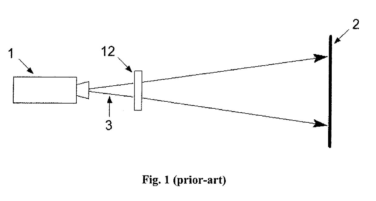
[0034]FIG. 1 shows a time-multiplexed stereoscopic 3d projection system based on a single image-beam architecture according to the state-of-the-art where a polarization modulator 12 comprising a stack of one or more liquid crystal elements (not shown) is placed directly in-front of the lens of a projector 1, such as a 3-chip DLP digital cinema projector or otherwise.

[0035]The projector 1 generates an incident image-beam 3 comprising a succession of alternate left and right-eye images at high frequency of typically 144 Hz and said polarization modulator 12 is typically arranged so as to impart a first circular polarization state to all left-eye images and a second circular polarization state to all right-eye images respectively, with said first and second circular polarization states being mutually orthogonal.

[0036]Thereaftr, said left and right-eye images are focused onto the surface of a polarization-preserving projection-screen 2 such as a silver-screen or otherwise, thereby enabl...


PUM


Abstract

The present invention relates to a time-multiplexed stereoscopic 3d projection system wherein the image-beam from a digital cinema projector is separated by a polarization beam-splitting element into one primary image-beam possessing a first state of polarization and at least one secondary image-beam possessing a second state of polarization. Polarization modulators are provided in order to modulate the polarization state for each of said primary and secondary image-beams thereof and arranged so that all left-eye images possess a first modulated state of polarization and all right-eye images possess a second modulated state of polarization. Additionally, there is provided one uniaxial condensing lens and at least one uniaxial expanding lens in order to minimize the optical path-lengths for each of said primary and secondary image-beams thereof, hence enabling said stereoscopic 3d projection system according to the present invention to operate together with projectors having a shorter throw-ratio as compared to other prior-art technologies.

Description

CROSS-REFERENCE TO RELATED APPLICATION[0001]This application claims the benefit of priority to U.S. Provisional Application No. 62 / 570,924, filed Oct. 11, 2017, which is incorporated herein by reference.FIELD OF INVENTION[0002]The present invention relates to a stereoscopic three dimensional (3d) projection system with a short throw-ratio, and more specifically to a time-multiplexed stereoscopic 3d projection system designed to provide a stereoscopic 3d image with good optical quality and on-screen homogeneity when used together with a digital cinema laser projector.BACKGROUND OF THE INVENTION[0003]Stereoscopic three dimensional (3d) projection systems have been used for many years. One technology known to the art and described, for example, in U.S. Pat. No. 7,528,906B2 dated 23 Jan. 2006 and entitled “Achromatic Polarization Switches”, describes how a polarization modulator can be placed in-front of a single-lens projector, such as a 3-chip DLP digital cinema projector or otherwise...

Claims


Application Information

Patent Timeline
Patent Type & Authority Applications(United States)
IPC IPC(8): G02B27/26G02B27/22G02B13/02G02B27/28G03B21/28G03B35/26G02B30/25
CPCG02B27/26G02B27/2264G02B13/02G02B27/283G03B21/28G03B35/26H04N13/337H04N13/341H04N13/363H04N9/3167G02B30/25G02B30/24H04N9/317
Inventor PALMER, STEPHEN
Owner VOLFONI R&D EURL
Why Eureka
Try Eureka