Tool bit for an ultrasonic osteotome

Inactive Publication Date: 2019-04-18
JIANGSU SMTP TECH CO LTD
View PDF1 Cites 8 Cited by
  • Summary
  • Abstract
  • Description
  • Claims
  • Application Information

AI Technical Summary

Benefits of technology

[0015]According to an embodiment of the tool bit for an ultrasonic osteotome of the present invention, a bottom surface of the grinding portion is inclined to an axis of the tool bit for an ultrasonic osteotome and intersects the axis of the tool bit for an ul

Problems solved by technology

When these two types of tool bits for an ultrasonic osteotome are used for grinding and removing bone, the amount of bone removed is large, the speed of operation is slow, and in addition, when performing a spinal open-door shaft side grinding, due to the specific shape of th

Method used


Image

  • Tool bit for an ultrasonic osteotome
  • Tool bit for an ultrasonic osteotome
  • Tool bit for an ultrasonic osteotome

Examples


Example

[0031]FIG. 1 is a schematic perspective view of a first embodiment of a tool bit for an ultrasonic osteotome of the present invention. FIG. 2 is a schematic front elevational view showing the first embodiment of the tool bit for an ultrasonic osteotome of the present invention. FIG. 3 is a schematic bottom plan view showing a first embodiment of the tool bit for an ultrasonic osteotome of the present invention. As shown in FIGS. 1-3, the tool bit for an ultrasonic osteotome according to the first embodiment of the present invention comprises a grinding portion 1 at a front end of the tool bit for an ultrasonic osteotome, and an arbor 2 with one end connected to the grinding portion 1 and the other end connected with a transducer for an ultrasonic osteotome. The arbor 2 may have a cylindrical shape, and a thread 6 for connecting with the transducer for an ultrasonic osteotome is provided at a tail end thereof. The thread 6 may be internally threaded or externally threaded according t...

Example

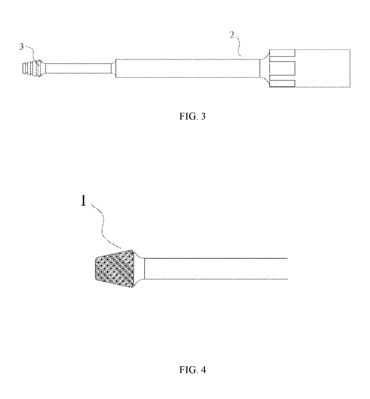
[0035]FIG. 4 is a schematic view of a grinding portion of a second embodiment of the tool bit for an ultrasonic osteotome of the present invention. In FIG. 4, a shape of the grinding portion 1 of the tool bit for an ultrasonic osteotome may be a trapezoidal prism which has a large rear end and a small front end, and the upper and lower surfaces are parallel to each other and parallel to an axis of the tool bit for an ultrasonic osteotome. Alternatively, a shape of the grinding portion 1 of the tool bit for an ultrasonic osteotome may be a trapezoidal cylinder, which has a large rear end and a small front end and has a trapezoidal shape in a section along the axis of the tool bit for an ultrasonic osteotome.

Example

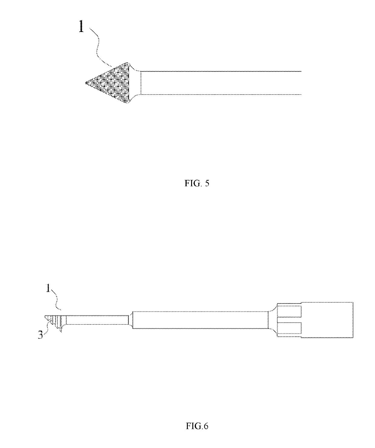
[0036]FIG. 5 is a schematic view showing a grinding portion of a third embodiment of the tool bit for an ultrasonic osteotome of the present invention. In FIG. 5, a shape of the grinding portion 1 of the tool bit for an ultrasonic osteotome may be a pyramid, which has a large rear end and a pointed front end, and the upper surface and lower surface thereof are parallel to each other and parallel to an axis of the tool bit for an ultrasonic osteotome. Alternatively, the shape of the grinding portion 1 of the tool bit for an ultrasonic osteotome may also be a pyramid or a cone having a large rear end and a pointed front end. A medical staff member can use different shapes of tool bits for an ultrasonic osteotome according to the needs of an operation.

[0037]In the tool bit for an ultrasonic osteotome shown in FIGS. 3 to 5, the grinding grooves 3 may be transverse grooves perpendicular to an axis of the tool bit for an ultrasonic osteotome, or skewed grooves formed at an angle with the ...


PUM


Abstract

Disclosed is a tool bit for an ultrasonic osteotome comprising a grinding portion at a front end of the tool bit, and an arbor with one end connected to the grinding portion and the other end connected with a transducer for an ultrasonic osteotome. The grinding portion has a tapered shape dwindling from a rear end toward a front end thereof and is connected with the arbor at the rear end thereof. A plurality of grinding grooves are provided on a bottom surface and side surfaces of the grinding portion, and a front surface of the grinding portion is a smooth surface. The tool bit has a tapered shape, which is small in structure, simple and flexible for operation, and convenient in use. When the tool bit is used for a surgery, ultrasonic energy is concentrated at a tip end, and a surgical window has a large field of view.

Description

CROSS REFERENCE TO RELATED APPLICATIONS[0001]This is a Continuation application of International Application Serial No. PCT / CN2017 / 086366, filed May 27, 2017, which claims the benefit of Chinese Application No. 201620555006.X, filed Jun. 8, 2016, the disclosures of which are hereby incorporated by reference.BACKGROUND[0002]The present disclosure relates to the field of medical instruments and devices, in particular to a scalpel, and more particularly to a tool bit for an ultrasonic osteotome.[0003]In modern society, with the development of medical technology, orthopedic surgery shows a trend of diversity. Accordingly, when performing a surgery, it is necessary to use different tool bits for a scalpel to perform cutting, grinding, scraping, clamping and other operations on an affected area in a patient according to different orthopedic conditions of disease.[0004]In view of the special construction of bone structure, along with the continuously development of ultrasound technology in...

Claims


Application Information

Patent Timeline
IPC IPC(8): A61B17/16
CPCA61B17/1659A61B17/1628A61B17/16A61B17/320068A61B2017/320073A61B17/1671A61B2017/00106A61B17/32
Inventor SUN, YUZHAN, SONGTAOCAO, QUN
Owner JIANGSU SMTP TECH CO LTD
Why Eureka
Try Eureka