
Sample preconcentration system and method for use with gas chromatography

a preconcentration system and sample technology, applied in sampling, laboratory glassware, instruments, etc., can solve the problems of affecting productivity, affecting productivity, and affecting the ability of other chemicals to interfere, so as to reduce or minimize bandwidth, reduce or eliminate the chance of water condensation, and increase or maximize sensitivity

Active Publication Date: 2019-04-25
ENTECH INSTR INC
View PDF0 Cites 5 Cited by
  • Summary
  • Abstract
  • Description
  • Claims
  • Application Information

AI Technical Summary

Benefits of technology

The patent describes a system and method that reduces the amount of gas sample needed for chemical analysis, such as gas chromatography. This leads to better sensitivity, as the system is able to inject the sample quickly and without losing important chemicals. The method also includes a dewpoint control to prevent water from condensing during the process. The system can be used with a wide range of samples, such as water and soil samples, food samples, and breath, blood, urine, or tissue samples. Overall, this patent provides a way to improve the efficiency and accuracy of chemical analysis for various applications.

Problems solved by technology

Loss of resolution can cause lower sensitivity and greater potential for interferences from other chemicals, for example.
Poor resolution caused by wide peaks also requires longer runs times in order to further separate compounds in the injection mixture, which can impact productivity while further increasing peak widths, as compounds can experience more diffusion-based band broadening the longer they remain on the column.
Compounds present at sub-PPB levels can still pose a toxicity risk, while other trace level compounds can both positively and negatively affect the flavor and odor of consumer products at part per trillion levels.
Although the techniques above can offer sensitivities below (e.g., are sensitive to compounds occurring in lower concentrations in the sample than) those offered by a 0.1 cc syringe or loop injection system, in some embodiments, they generally cannot transfer the sample fast enough to a typical GC column flowing at just 0.5-3 cc / min while maximizing the resolution of lighter compounds.
Fast injection rates may not be possible using the above-listed sample introduction techniques due to size of the adsorbent bed or due to the initial volume of the sample.
This approach can have two problems, however.
First, liquid nitrogen is falling out of favor in some laboratories due to cost and safety concerns, and, for these reasons and others, many laboratories simply cannot use liquid nitrogen.
Secondly, focusing using liquid nitrogen will retain all of the moisture in the sample, causing interferences during GC and GCMS analysis.
Too much water (e.g., approximately 10 cc or more of a gas sample at 100% relative humidity at 25° C.) can suppress the signal in the mass spectrometer, and can often also affect the resolution and peak shape of compounds during gas chromatography.
Many gas samples can also contain large amounts of carbon dioxide (CO2) that may not be eliminated using cryogenic focusing traps, which can cause chromatography problems and additional detector suppression.
This kind of trap can reduce the amount of water and CO2 in the sample, and can lower the injection volume, but it is not effective at removing all of the moisture from the sample, and may not release the sample fast enough to obtain optimum peak widths on the capillary GC column.
This larger particle volume requires a longer period of time for compounds to diffuse out of the particle even at higher desorption temperatures, which in turn increases the peak widths, and can even cause undesirable peak “tailing” as the final 5-20% of the chemicals “bleed” out of the larger particles.
The down side of split injections is that 95% of the sample is discarded via the split port, making it more difficult to reach required detection limits because less of the sample is provided to the detector.
As another example, SPME, which is a technique that uses a small fiber to collect sample, may not collect very much water and may desorb relatively fast without focusing or splitting, but can suffer from poor reproducibility in many matrices, and often cannot recover the lighter chemicals of interest.

Method used


Image

  • Sample preconcentration system and method for use with gas chromatography
  • Sample preconcentration system and method for use with gas chromatography
  • Sample preconcentration system and method for use with gas chromatography

Examples


Embodiment Construction

[0027]In the following description, reference is made to the accompanying drawings which form a part hereof, and in which it is shown by way of illustration specific examples that can be practiced. It is to be understood that other examples can be used and structural changes can be made without departing from the scope of the examples of the disclosure.

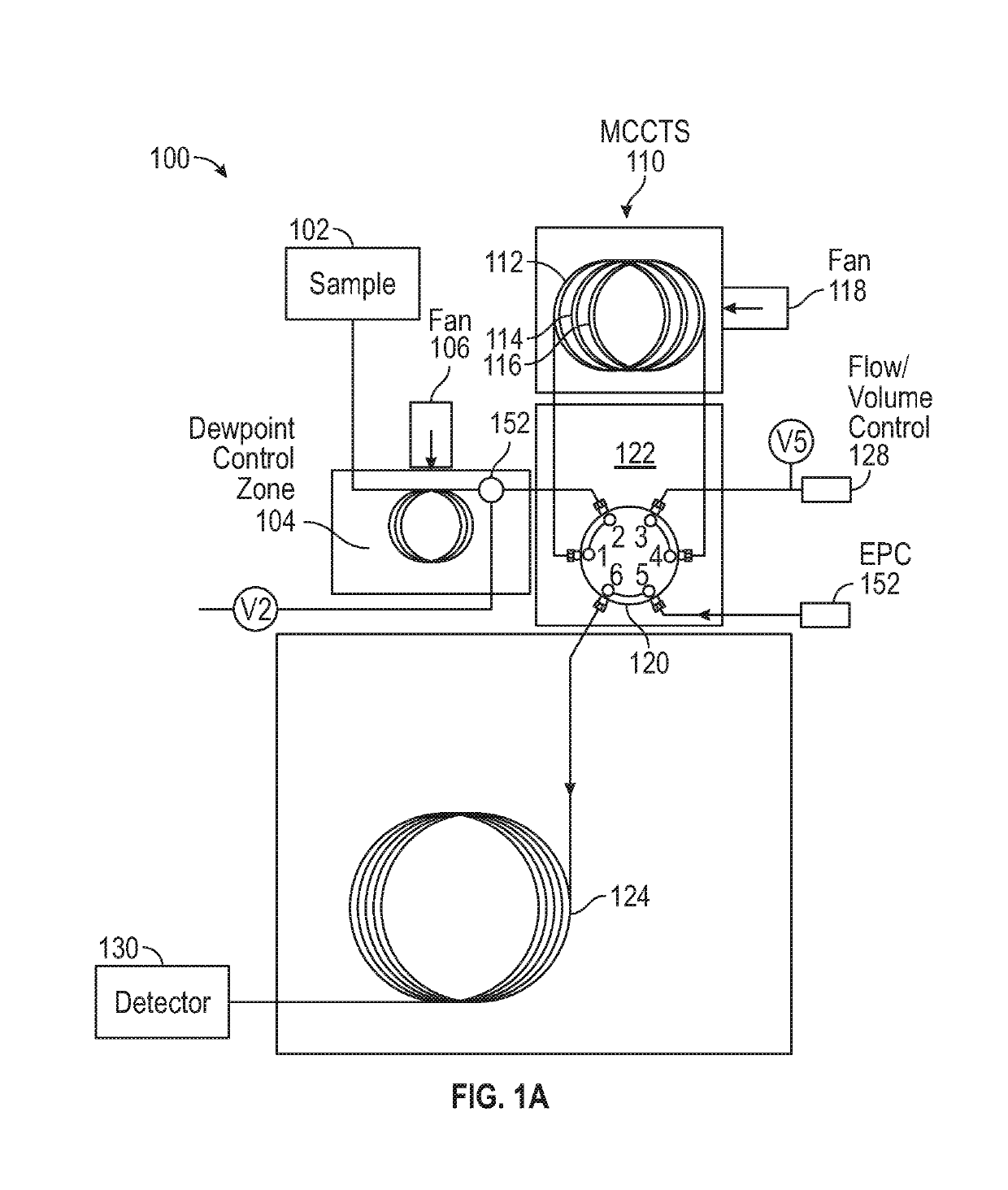
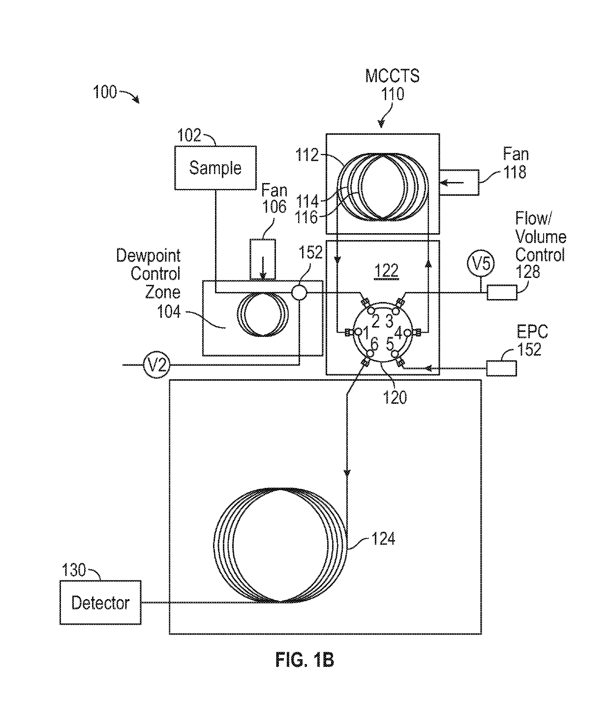
[0028]FIGS. 1A-B illustrate an exemplary system 100 according to some embodiments of the disclosure. System 100 can be used to focus a sample in a way that allows it to be released into 0.1 cc of carrier gas during desorption for rapid, split-less injection into a chemical separation column (e.g., a GC column) while eliminating water and any carbon dioxide in the sample prior to injection.

[0029]As shown in FIGS. 1A-1B, the system 100 optionally includes a sample 102, a dewpoint control zone 104, a fan 106 proximate to the dewpoint control zone 104, a six-position rotary valve 120 situated in heater 122, a multi-capillary column trappi...


PUM


Abstract

The disclosed system and method concentrates and enriches a chemical sample while removing water and / or CO2 prior to analysis, improving detection limits and repeatability of quantitative chemical analysis without the need for cryogenic or sub-ambient cooling. The system can include a valve system, a dewpoint control zone, and a multi-capillary column trapping system (MCCTS). During a first time period, the valve system can couple the dewpoint control zone to the MCCTS. During a second time period, the valve system can couple the MCCTS to the chemical separation column such the dewpoint control zone is bypassed. Excess water included in the sample can condense in the dewpoint control zone as the sample transfers to the dewpoint control zone and MCCTS. When the sample is transferred from the MCCTS to the chemical separation column, the condensed water in the dewpoint control zone is not transferred to a chemical separation column.

Description

CROSS-REFERENCE TO RELATED APPLICATIONS[0001]This application claims the benefit of U.S. Provisional Patent Application No. 62 / 576,769, filed on Oct. 25, 2017, the entire disclosure of which is incorporated herein by reference in its entirety for all purposes.FIELD OF THE DISCLOSURE[0002]This relates to a system and method of preconcentrating a sample for subsequent chemical analysis, such as by gas chromatography or gas chromatography-mass spectrometry.BACKGROUND OF THE DISCLOSURE[0003]Analysis of trace level VOCs and other volatile chemicals by gas chromatography and gas chromatography-mass spectrometry can require preconcentration prior to injection into a chemical analysis device (e.g., GC or GCMS (Gas Chromatograph / Mass Spectrometer)) in order to detect compounds that have concentrations below about 50 PPBv. In some embodiments, GCs operate using a capillary GC column with flow rates in the range of 0.5-3 cc / min, and typical peak widths eluting from the columns of 2-8 seconds w...

Claims


Application Information

Patent Timeline
IPC IPC(8): B01L3/00G01N1/40G01N1/44G01N30/12G01N30/14G01N30/30G01N30/46G01N30/72
CPCB01L3/502G01N1/405G01N1/44G01N30/12G01N30/14G01N30/30G01N30/461G01N30/7206B01L2300/0838B01L2300/18G01N2030/121G01N30/6078G01N1/2214G01N30/08G01N30/20G01N2001/4033
Inventor CARDIN, DANIEL B.
Owner ENTECH INSTR INC
Learn More