Structural reinforced composite construction mat

Active Publication Date: 2019-05-09
PLASTIC TIES TECH LLC
View PDF5 Cites 0 Cited by
  • Summary
  • Abstract
  • Description
  • Claims
  • Application Information

AI Technical Summary

Benefits of technology

[0005]A composite construction mat constructed according to one preferred embodiment of the invention comprises a plurality of beams fabricated of plastics-based composite material and arranged side-by-side. The mat further includes a plurality of flitch plates that are arranged between at least some of the composite beams. The beams and flitch plates are tied together with a plurality of cross rods. The flitch plates are made of a material that is stiffer than that of the beams and is likewise moisture resistant to enhance the overall structural rigidity and beam strength beyond what the composite beams alone would provide.
[0006]The structural reinforced composite mat constructed accordingly has the advantage of being lighter, stronger and longer lasting than timber construction mats and it does not lose strength in prolonged wet conditions, nor does it absorb water, rot or otherwise deteriorate. The mat can be pre-engineered to the strength and load requirements of a particular job and will maintain its properties throughout its service life, unlike wood.
[0007]The structural reinforced composite mat constructed according to the invention is about 25% lighter than a mat of comparable beam size made of timber. This leads to a surprising and beneficial reduction in transportation costs and increased ease of handling on the job site. For example, a 12″ thick timber mat for standard heavy construction, when dry, is about 40% heavier than a 7″ structural reinforced composite mat made according to the invention. A structural reinforced composite mat made according to the invention surprisingly exceeds the load capacity of 12″ tim

Problems solved by technology

The beams are often made of timber (e.g., red oak or mixed hardwood) which is readily available and inexpensive, but has a tendency to become water logged and heavy and are prone to fungus and insect attack, rotting and deterioration, especially in extremely harsh, wet applications, greatly limiting their useful service life.
The timber beams also lose their strength and integrity in wet conditions and can be quickly eroded under the l

Method used


Image

  • Structural reinforced composite construction mat
  • Structural reinforced composite construction mat
  • Structural reinforced composite construction mat

Examples


Embodiment Construction

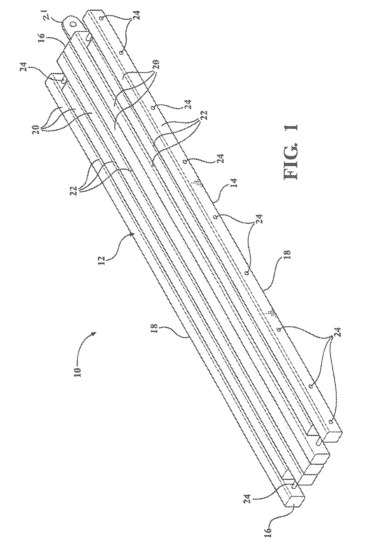
[0029]A structural reinforced composite mat constructed according to an embodiment of the invention is generally shown in perspective view in FIG. 1 and indicated by reference numeral 10.

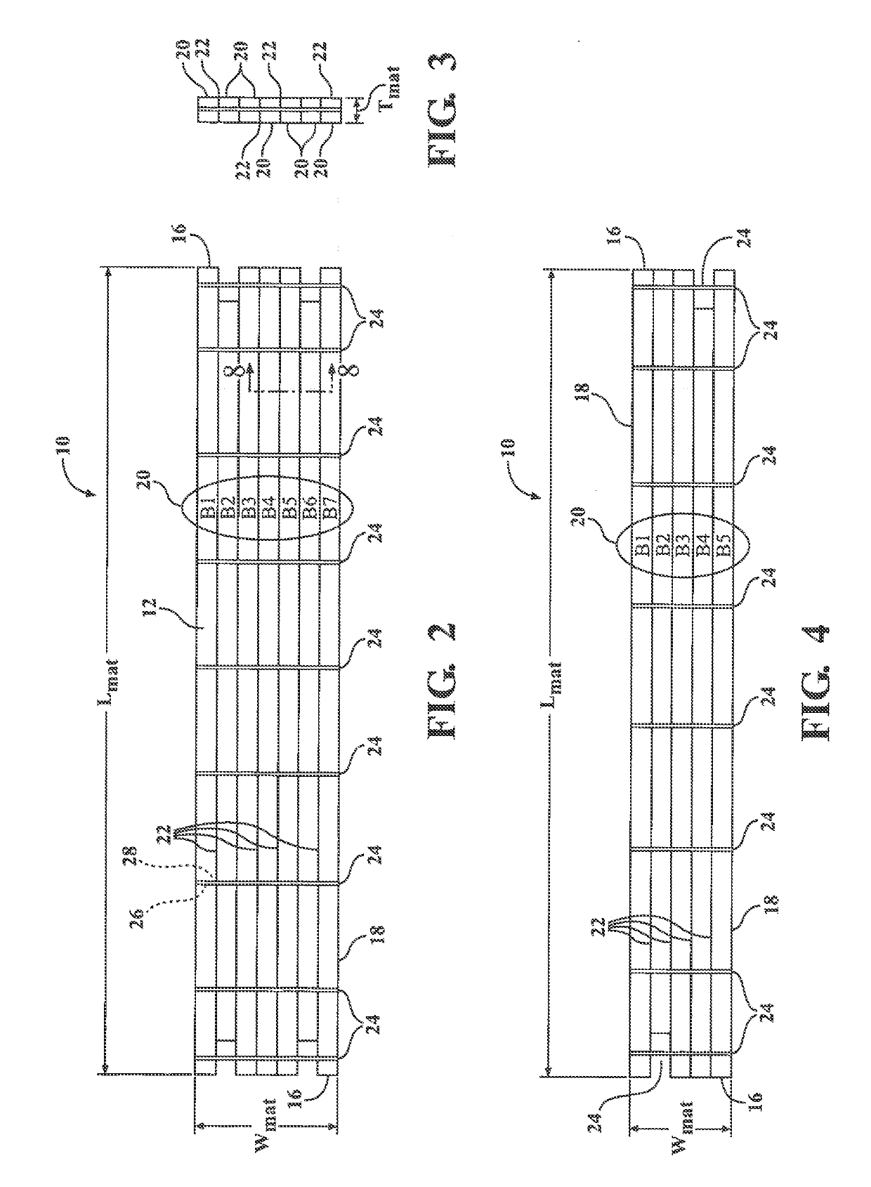
[0030]The mat 10 has a top surface 12, a bottom surface 14, longitudinally opposite ends 16 and laterally opposite sides 18. The mat 10 has an overall length dimension Lmat extending between the two ends 16, an overall width dimension Wmat extending between the two sides 18, and an overall thickness Tmat dimension extending between the top 12 and bottom 14 surfaces. An exemplary mat 10 may have an overall Tmat×Wmat×Lmat measurement of 9 inches×51 inches×24 feet. All of these dimensions can vary depending upon the needs of a particular application. A mat according to an alternative embodiment (FIG. 4) may have overall dimensions of 7″×46″×20′.

[0031]Throughout the figures, it will be appreciated that dimensional references are exemplary in nature, and that the arrangements illustrated in the figures m...


PUM


Abstract

A structural reinforced composite construction mat includes a plurality of composite plastic beams that are ganged together to define the mat, with a plurality of flitch plates disposed between at least some of the plastic beams to provide additional strength and rigidity to the mat. The plastic beams may be made of a composite material have a generally rectangular cross-section. The flitch plates have a width (vertical height) when disposed between adjacent beams that is less than the width (vertical height) of the beams, such that the flitch plates may be recessed below and above the top and bottom surfaces of the mat, respectively. A plurality of rods extend in the lateral direction through the beams and plates to compress the beams and plates against each. The flitch plates may be metal or fiber-reinforced resin and may further include slotted holes to allow the beams to retract lengthwise in response to environmental changes.

Description

CROSS-REFERENCE TO RELATED APPLICATIONS[0001]This application claims the benefit of U.S. Provisional Patent Application No. 62 / 581,254, filed Nov. 3, 2017, the contents of which are hereby incorporated by reference in their entirety.BACKGROUND OF THE INVENTION1. Technical Field[0002]This invention relates generally to construction mats and particularly to construction mats made of composite materials.2. Related Art[0003]Construction mats are often utilized in gas and oil drilling and completion rig sites, as work platforms, wet job sites, as access roads in difficult terrain or environmentally sensitive environments, such as wet lands. The mats are typically made up of several heavy beams that are tied together by a series of metal rods. The beams are often made of timber (e.g., red oak or mixed hardwood) which is readily available and inexpensive, but has a tendency to become water logged and heavy and are prone to fungus and insect attack, rotting and deterioration, especially in ...

Claims


Application Information

Patent Timeline
IPC IPC(8): E04B1/24B27D1/10
CPCE04B2001/2406E04B1/2403E04B2001/2415E04B2001/2457B27D1/10E01C5/22E01C9/08E04C2/40E04C3/29E04B5/026B32B2471/04
Inventor BROWN, JR., CLAUDECRANE, DAVID C.COMBS, ROBERT E.
Owner PLASTIC TIES TECH LLC
Why Eureka
Try Eureka