Depressurisation method and apparatus for subsea equipment

a technology of subsea equipment and depressurisation method, which is applied in the direction of fluid removal, earth-moving drilling, and well accessories, etc., can solve the problems of affecting the operation of the equipment, and restricting the flow of produced fluid, so as to reduce the pressure of the remaining fluid, avoid the high hydrostatic pressure, and easy to install

Active Publication Date: 2019-05-09
TECHNIP UK
View PDF6 Cites 12 Cited by
  • Summary
  • Abstract
  • Description
  • Claims
  • Application Information

AI Technical Summary

Benefits of technology

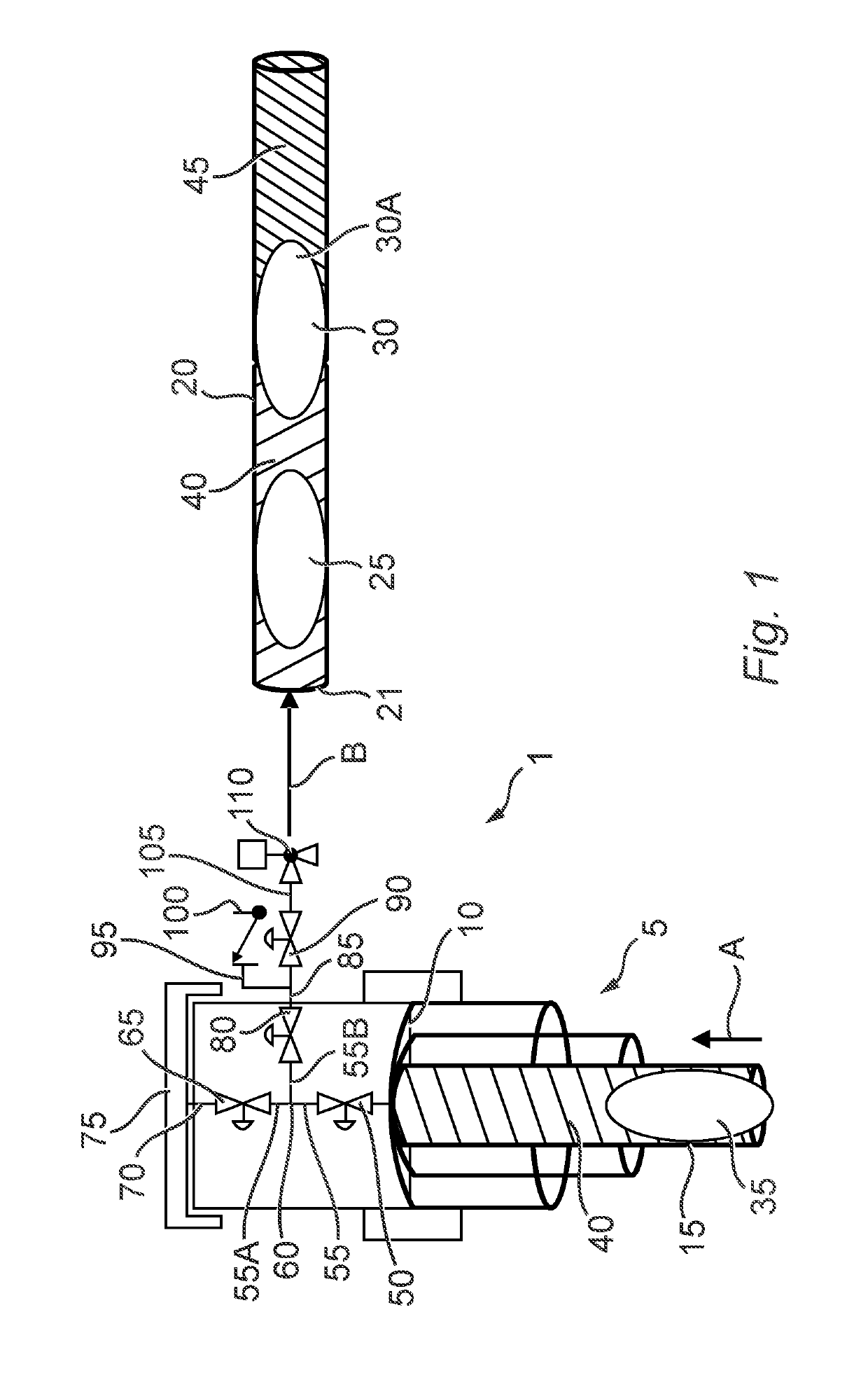
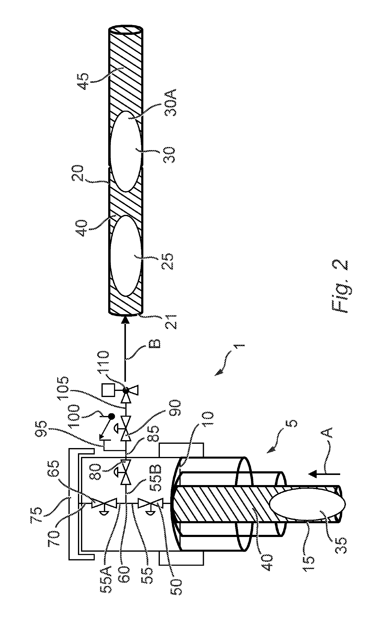
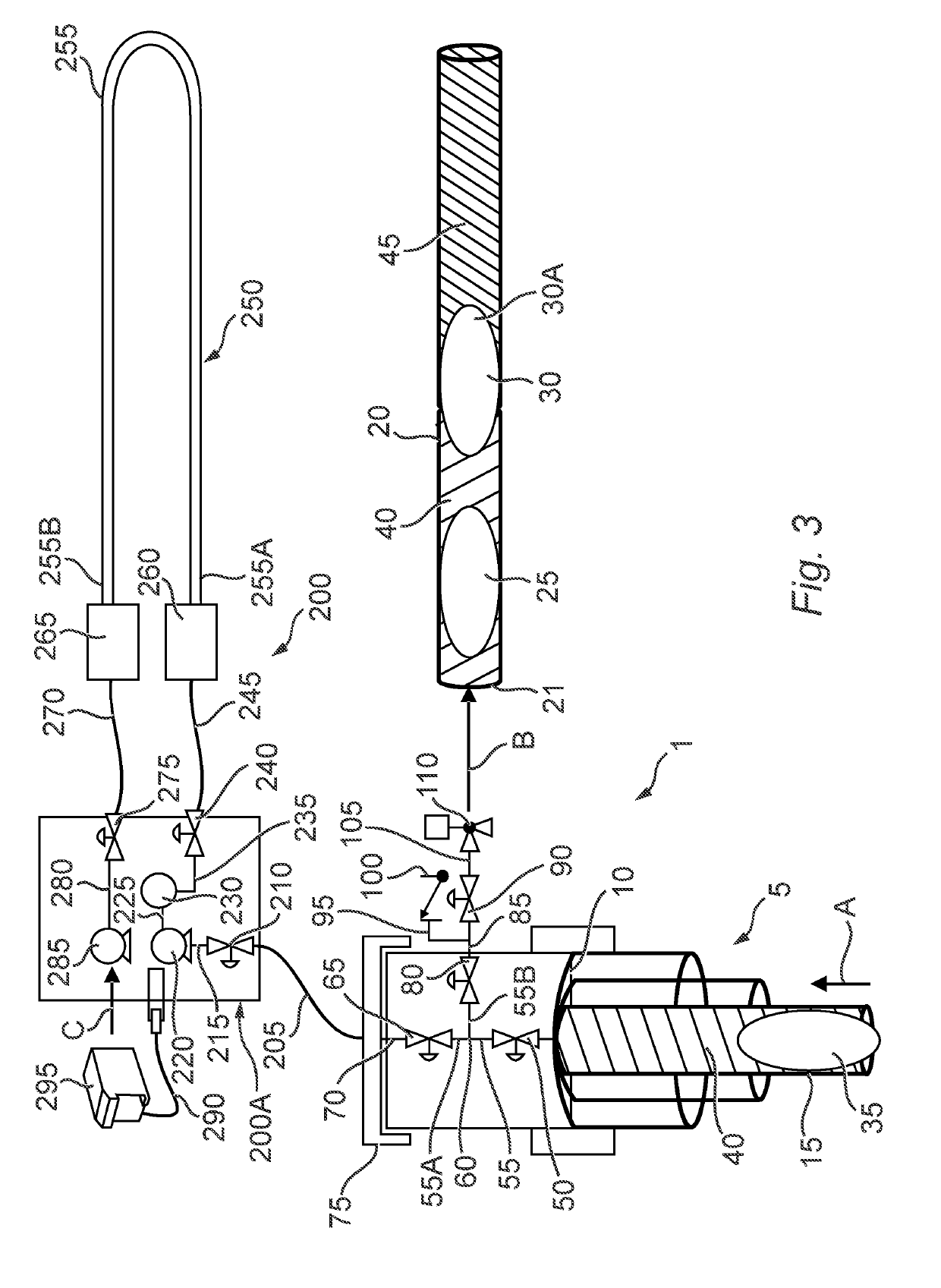
[0020]The method does not involve the use of a riser for extracting the fluid to a topside vessel, thereby avoiding the high hydrostatic pressure that this can generate in the resulting column of fluid (for example, a 2000 m fluid column in the prior art can result in a pressure of 200 bar (20 MPa)). Instead, it allows fluid from the subsea equipment to be extracted into the pipe, which is generally laid on the sea floor, in order to reduce the pressure of the fluid remaining in the subsea...

Problems solved by technology

The formation of hydrates in subsea equipment can restrict the flow of produced fluid through that equipment.
In the worst cases, this can lead to the blockage of the flow through the subsea equipment, as well as damage to pumps and/or valves which may cause them to stop working.
However, these known methods all have drawbacks.
A disadvantage of this operation is that it is limited to use in pipelines and cannot be utilised to remove hydrates from manifolds or Christmas Trees.
However, a drawback of this process is that because hydrate deposits are not porous the chemicals cannot penetrate and break up existing hydrate deposits.
Thus, this chemical method does not provide a complete solution, especially when the hydrate is already formed.
Again, a disadvantage of this operation is that whilst it can be utilised in pipelines it is not practical to use it in areas such as manifolds or Christmas Trees.
Drawbacks of this process include that the equipment required to carry it out is expensive and not always available.
Also, it can be technically difficult to return the fluid to the flowline.
In addition, the fact that pressurised fluid is transported onto a vessel ...

Method used


Image

  • Depressurisation method and apparatus for subsea equipment
  • Depressurisation method and apparatus for subsea equipment
  • Depressurisation method and apparatus for subsea equipment

Examples


Embodiment Construction

[0041]It has been surprisingly found by the inventors that improved removal of hydrates from subsea equipment can be provided using the methods and apparatus of the invention. Many of the existing methods of removing hydrates involve the use of dedicated vessels. For example, a first dedicated vessel is required for the deployment and recovery of the apparatus used in these known methods, whilst a second dedicated vessel is needed when carrying out the method (ie the depressurisation phase). This second vessel needs to be capable of recovery and on-board storage of the depressurised production fluid from the subsea equipment. The availability of such vessels can be limited, and in addition their use adds cost. The methods and apparatus of the invention do not require a specially adapted vessel and can therefore reduce costs. Instead, they can be laid and operated by the same single vessel, which does not need to be capable of storing the production fluid from the subsea equipment.

[0...


PUM


Abstract

A method for reducing the pressure of fluid within subsea equipment. The method includes the steps of: (a) providing a pipe, (b) laying the pipe on the sea floor, (c) providing a connector, (d) connecting the pipe to the subsea equipment via the connector, and (e) extracting fluid from the subsea equipment through the connector and into the pipe. Apparatus for reducing the pressure of fluid within subsea equipment by extracting fluid from the subsea equipment.

Description

[0001]This invention relates to a method for reducing the pressure of fluid within subsea equipment. It also relates to apparatus for the remediation of hydrate by reducing the pressure of fluid within subsea equipment, a method for connecting the apparatus to subsea equipment, and a method of deploying the apparatus.BACKGROUND[0002]When fluid is extracted from a subsea oil and gas well, the fluid produced is normally conveyed from the wellbore to a production facility, for example a Floating Production Storage and Offloading vessel (FPSO) located on the surface of the ocean (also known as topside), via various items of subsea equipment. Typically, the subsea equipment includes a Christmas Tree, which is an assembly of valves, spools and pressure gauges fitted to the wellhead to control production.[0003]During the production of fluid from the subsea oil and gas well, the produced fluid is transported through pipelines which may comprise two parts, (i) a flowline, which is the portio...

Claims


Application Information

Patent Timeline
IPC IPC(8): E21B43/013
CPCE21B43/013F16L55/26F16L2101/20F16L2101/70E21B43/01E21B31/00E21B37/00E21B37/06
Inventor ESPINASSE, PHILIPPE FRANCOISPARENTEAU, THOMASMARRET, ANTOINE
Owner TECHNIP UK
Why Eureka
Try Eureka