Flag mushroom cup nozzle assembly and method

a mushroom cup and nozzle technology, applied in the direction of spray nozzles, spray apparatus, etc., can solve the problems of fines or nearly atomized droplets, poor control of spray droplet sizes, and limited control of spray pattern

Active Publication Date: 2019-05-16
DLHBOWLES INC
View PDF0 Cites 1 Cited by
  • Summary
  • Abstract
  • Description
  • Claims
  • Application Information

AI Technical Summary

Benefits of technology

[0011]Accordingly, it is an object of the present invention to overcome the above-mentioned difficulties by providing a commercially reasonably inexpensive, disposable, manually actuated, cup-shaped nozzle assembly adapted for use with a flag-mushroom fluidic circuit to provide precise sprayed droplet size control and precisely defined spray sheets or flat fan shaped spray patterns when spraying viscous, shear-thinning liquids or fluid products.
[0012]The flag mushroom cup nozzle assembly of the present invention is configured as a cup and housing package somewhat similar to that illustrated in the prior art of FIGS. 1A-1C, but incorporates a nozzle assembly in an actuator body having a fluidic circuit configured to spray an oscillating sheet of fluid product droplets distally from a sprayer housing instead of the conical spray with a circular cross-section produced by the FIGS. 1A-1C device. This configuration, which can be adapted to provide multi-lip and multi-power nozzle embodiments, generates a spray of shear thinning and high viscosity fluids with even distribution. The packaging concept and method of the present invention allow easier molding of small fluidic circuits because the circuit features are defined or “shared” between two larger molded pieces rather than having all of the fluidic circuit features defined in one molded piece.
[0013]The nozzle assembly and cup member of the present invention differs from Applicants' prior work (as illustrated in FIG. 1D), in that the invention incorporates a distinctive housing and sealing package, as well as a distinctive fluidic circuit geometry molded into the cup member. Thus, the flag mushroom cup assembly of the present invention effectively splits the operating features of the fluidic circuit between a lower or proximal portion formed in the housing's sealing post member and an upper, or distal portion formed in the cup member. The assembly of the present invention is made possible by configuring the packaging and design of a flag mushroom fluidic circuit to provide a conformal cup-shaped member that ideally is well suited for use with a novel sealing post member, where the new combination is then adapted for integration with commercial spray nozzle assembly components like those described in the prior art and illustrated in FIGS. 1A-1F.
[0018]The fluid supply lumen enables fluid product to flow from a container and into fluidic geometry defined between the flag mushroom cup member and the cooperating sealing post, which together define a chamber having an interaction region between the sealing post and the peripheral wall and distal walls of the cup-shaped member. The chamber is in fluid communication with the actuator body fluid passage to define a fluidic circuit oscillator inlet so the pressurized fluid can enter the chamber and interaction region. The flag mushroom cup structure has for example, first and second fluid inlet passageways of substantially constant cross section within the proximally projecting cylindrical sidewall of the cup member; however, these exemplary first and second fluid inlets can alternatively be tapered or include step discontinuities (e.g., with an abruptly smaller or stepped inside diameter) to enhance pressurized fluid instability.
[0022]The cup member's interaction region and exit orifice or throat are preferably molded directly into the cup's interior wall segments. When molded from plastic as a cup-shaped member, the flag mushroom cup is easily and economically fitted onto the actuator's cooperating indexed sealing post, which typically has a distal or outer face that is in sealing engagement with the cup-shaped member's distal wall's inner face in a substantially fluid impermeable contact. The peripheral walls of the sealing post and the cup-shaped member are spaced radially to define an annular fluid channel around the post. The peripheral walls are generally parallel with each other but the space between them may be tapered to aid in developing greater fluid velocity and instability. Whatever the configuration, when the cup-shaped member is fitted to the indexed sealing post and pressurized fluid is introduced, (e.g., by pressing the aerosol spray button and releasing the propellant), the pressurized fluid enters the fluid channel chamber and interaction region and generates at least one oscillating flow vortex within the fluid channel interaction region.
[0023]The flag mushroom cup nozzle assembly of the present invention is configured to spray shear thinning liquids with an even distribution of small droplets. The nozzle assembly is adapted for commercial aerosol sprays like paints, oils, and lotions, and in use generates an even flat fan spray with more uniform and smaller droplets than similar prior art nozzles can generate. The flag mushroom cup nozzle assembly of the present invention, when spraying, does not create voids or hotspots, and also allows for the use of aeration.

Problems solved by technology

These prior art nozzle assembly or spray-head structures with swirl chambers are configured to generate substantially conical atomized or nebulized sprays of fluid or liquid in a continuous flow over the entire spray pattern; however, in such devices the spray droplet sizes are poorly controlled, often generating “fines” or nearly atomized droplets as well as larger droplets.
Other spray patterns such as, for example, a narrow oval which is nearly linear, are possible, but the control over the spray's pattern is limited.
None of these prior art swirl chamber nozzles can generate an oscillating sheet spray of liquid nor can they provide precise sprayed droplet size control or sheet spray pattern control.
The Applicants have been approached by liquid product makers who want to provide those advantages, but available prior art fluidic nozzle assemblies have not been configured for incorporation with disposable, manually actuated sprayers.
Meeting such needs has led to Applicants' related applications and patents incorporating fluidic circuits in Cup-shaped members, such as WIPO Pub WO 2012 / 145537 and U.S. Pat. No. 9,089,856 (which includes illustrations corresponding to FIGS. 1A-1F, provided here for enablement and to illustrate the configurations and nomenclature of applicants' prior work), but these nozzle configurations are not well suited to generating flat sprays of highly viscous fluids such as paint or lotion.
More specialized fluidic circuit generated sprays for highly viscous fluids could be very useful in disposable sprayers, but adapting the fluidic circuits and fluidic circuit nozzle assemblies of the prior art would cause additional engineering and manufacturing process changes to the currently available disposable, manually actuated sprayers, thus making them too expensive to produce at a commercially reasonable cost, especially when the sprayers are intended for single-use spraying.

Method used


Image

  • Flag mushroom cup nozzle assembly and method
  • Flag mushroom cup nozzle assembly and method
  • Flag mushroom cup nozzle assembly and method

Examples


Embodiment Construction

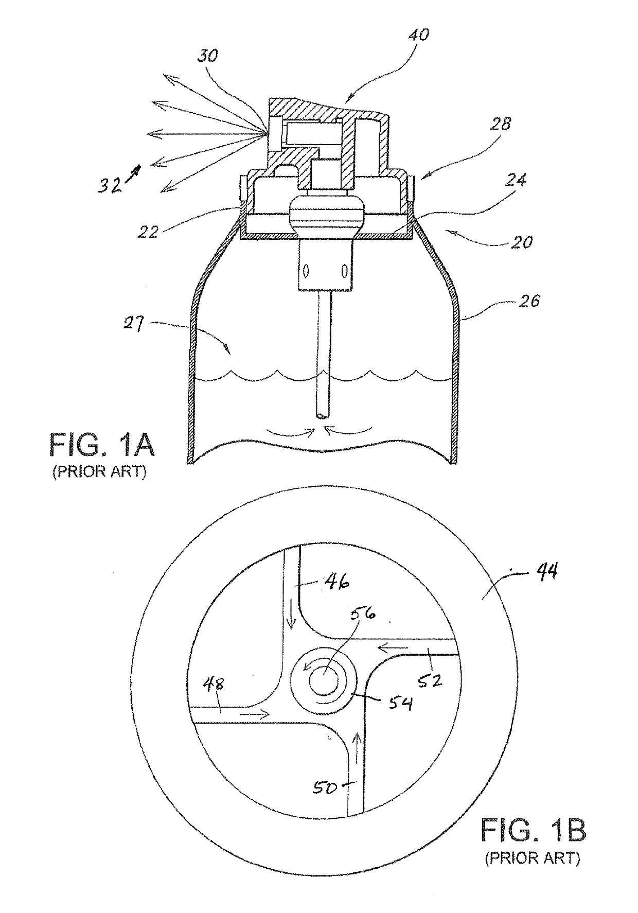
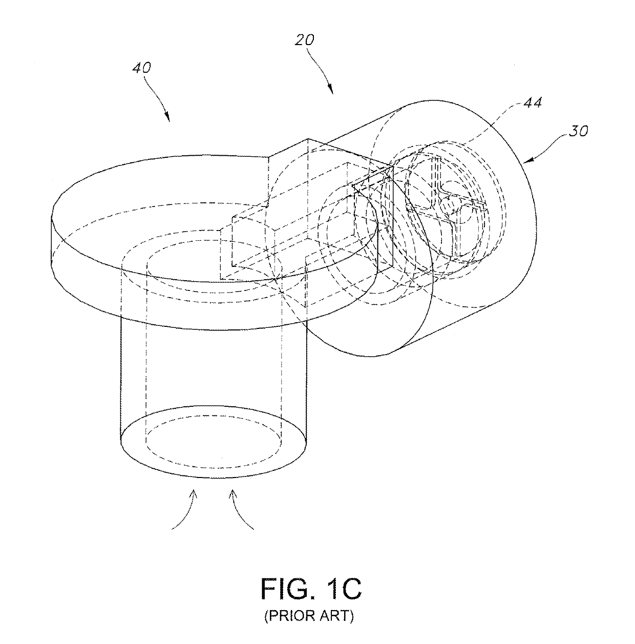
[0045]To provide background for the present invention, reference is first made to FIGS. 1A-1F show typical features of aerosol spray actuators and swirl cup nozzles used in the prior art, and these figures are described here to provide added context for the novel features of the invention. Referring specifically to FIG. 1A, a transportable, disposable propellant pressurized aerosol package 20 has a container 26 enclosing a liquid product 27 under pressure and an actuator 40 which controls a valve 42 mounted within a valve cup 24 which is affixed within a neck 28 of the container and supported by container flange 22. In operation, the actuator 40 is depressed to open the valve to allow pressurized liquid to flow through a swirl-cup equipped nozzle 30, thereby producing an aerosol spray 32. FIG. 1B illustrates the inner workings of a swirl cup 44 taken from a typical nozzle such as the nozzle 30, wherein four lumens 46, 48, 50, 52 are aimed to cause four tangential pressurized liquid ...


PUM


Abstract

An alignable conformal, cup-shaped flag-mushroom fluidic nozzle assembly is engineered to generate a flat fan or sheet oscillating spray of viscous fluid product 316. The nozzle assembly includes a cylindrical flag mushroom fluidic cup member 180 having a substantially closed distal end wall with a centrally located snout defined therein. The flag mushroom cup assembly effectively splits the operating features of the fluidic circuit between a lower or proximal portion formed in the housing's sealing post member and an upper, or distal portion formed in cup member 180 which, in cooperation with the sealing post's distal surface, defines an interaction chamber 192 fed by impinging jets each comprising a continuous distribution of streamlines that impinge at selected angles to define arcs providing a lesser degree of impingement at a centered axial plane within the exit orifice 194 and a greater degree of impingement at the edges of exit orifice 194.

Description

REFERENCE TO RELATED APPLICATIONS[0001]This application claims priority to commonly owned U.S. provisional patent application No. 62 / 331,065, filed 3 May 2016, the entire disclosure of which is hereby incorporated herein by reference. This application is also related to commonly owned U.S. provisional patent application No. 61 / 476,845, filed Apr. 19, 2011 and entitled “Method and Fluidic Cup Apparatus for Creating 2-D or 3-D Spray Patterns”, as well as PCT application number PCT / US12 / 34293, filed Apr. 19, 2012 and entitled “Cup-shaped Fluidic Circuit, Nozzle Assembly and Method” (now WIPO Pub WO 2012 / 145537), U.S. application Ser. No. 13 / 816,661, filed Feb. 12, 2013, and commonly owned U.S. Pat. No. 9,089,856, the entire disclosures of which are also hereby incorporated herein by reference.BACKGROUND OF THE INVENTIONField of the Invention[0002]The present invention relates generally to nozzle assemblies adapted for use with transportable or disposable liquid product sprayers, and mo...

Claims


Application Information

Patent Timeline
Patent Type & Authority Applications(United States)
IPC IPC(8): B05B1/08B05B12/06B05B1/34
CPCB05B1/08B05B12/06B05B1/34
Inventor HASDAY, BENJAMIN D.HARTRANFT, EVAN
Owner DLHBOWLES INC
Why Eureka
Try Eureka