
Optical rotation angle measuring system

a technology of rotation angle and measuring system, which is applied in the field of optical systems, can solve the problems of 67 microradians, inability to avoid the order of a few micrometers, and inability to meet the measurement resolution now required, and achieves the effect of reducing the number of micrometers, and increasing the measurement rang

Active Publication Date: 2019-05-16
ARGES GMBH
View PDF0 Cites 3 Cited by
  • Summary
  • Abstract
  • Description
  • Claims
  • Application Information

AI Technical Summary

Benefits of technology

The invention is an optical rotation angle measuring device that is more accurate, compact, and tolerant to transverse displacement of the rotation shaft than previous devices. The diffraction element in the device is smaller and the information content is smaller than previous devices, which reduces the inertial load on the angular decoder. The illumination beam should be positioned on the axis of rotation of the rotation shaft of the angular decoder, but the source of the illumination can also be positioned off the axis. The system is tolerant to changes in the wavelength of the illumination source and the temperature of the system. The position error caused by expansion of the shaft can be tolerated up to 70 μm, and the system can be made more tolerant by adding a spherical mirror to make the detector plane flat and perpendicular to the system's symmetry axis.

Problems solved by technology

In practice it appears that such displacements of the order of a few micrometers cannot be avoided.
If r=15 mm a displacement of the cylindrical grating over 1 μm will cause an error in angle measurement of 67 microradians, which is unacceptable in view of the measurement resolution now required.
Moreover, because of its optical outlay and the number of optical elements, the device of DE Patent 10 2011 050 030 cannot be made compact and lightweight.

Method used


Image

  • Optical rotation angle measuring system
  • Optical rotation angle measuring system
  • Optical rotation angle measuring system

Examples


Embodiment Construction

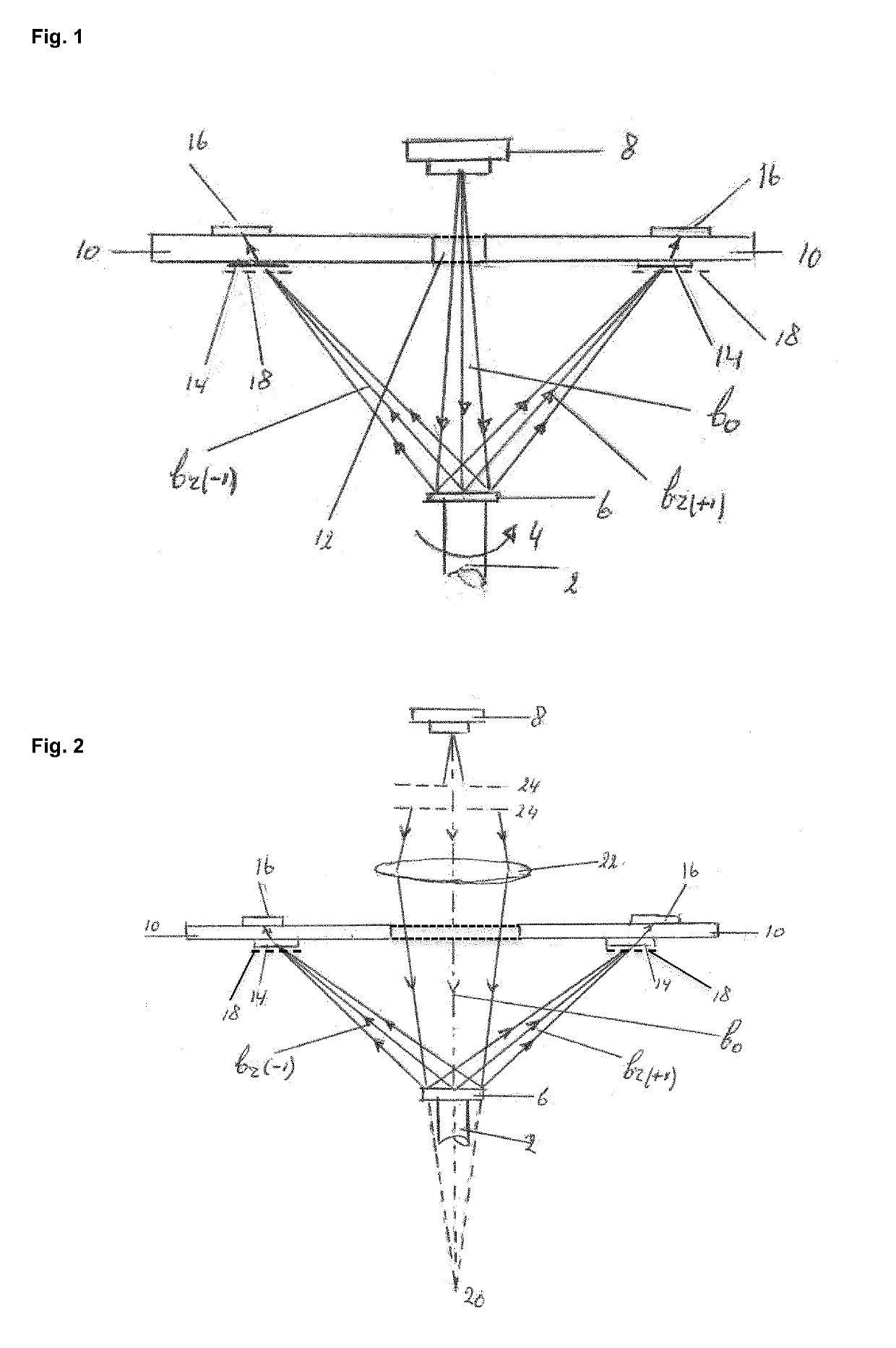
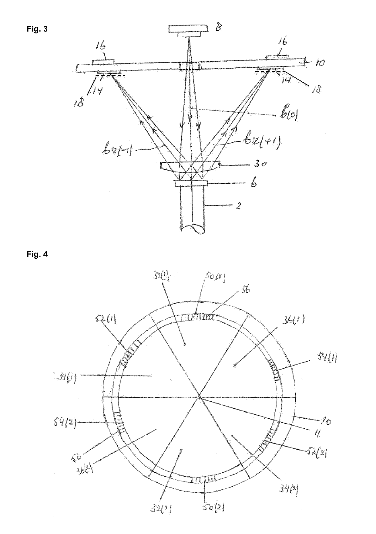
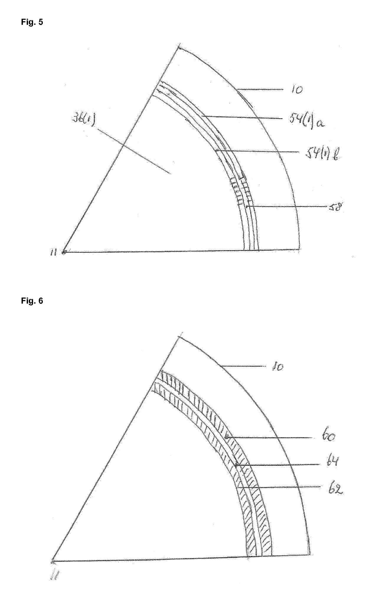
[0041]FIG. 1 shows the principle diagram of the rotation angle measurement system according to the drawings, which is, for example suitable for measuring the angular position of a galvanometer scanner. The rotation shaft of this scanner is denoted by reference number (2). The mirror (not shown in the Figure) of the scanner is mounted on this shaft, which rotation movement is indicated by arrow (4), but should not be understood as limiting the invention to a single direction of rotation. The rotation shaft can rotate in either direction. On one end face of the shaft and perpendicular to the shaft a small and reflective diffraction element (RDE) (6), in particular a hologram (31) is mounted. The diffraction element (6) is illuminated by a spherical radiation beam bo emitted by a monochromatic radiation source, preferably a diode laser (8), which is arranged in line with the rotation axis of shaft (2). The diffraction element splits incident beam bo in sub-beams of different diffractio...


PUM


Abstract

The present invention is directed to an optical system for measuring the rotation angle of rotatable object having a rotation shaft (2), which system comprises a reflective diffraction element (6) mounted on said shaft and a module that includes a radiation source (8) emitting a monochromatic beam (bo) towards this element and a radiation-sensitive detection structure (14, 16), the diffraction element is configured to project diffraction order images (18) of its pattern onto associated sections (50(1)-54(2)) of an annular grating structure forming part of the detection structure and the surface size of the diffraction element is smaller than 20% of the surface size of the annular grating structure.

Description

FIELD OF THE INVENTION[0001]The invention relates to an optical system for measuring the rotation angle of a rotatable object having a rotation shaft, which system includes at the one hand a reflective diffraction element mounted on the shaft and rotating with the shaft and at the other hand a radiation source and detection module, which module comprises:[0002]a radiation source emitting an illumination beam of nearly monochromatic radiation towards the diffraction element; and[0003]a radiation-sensitive detection structure, comprising an annular grating mask, converting illumination beam radiation reflected by the diffraction element into electrical signals suitable for electronic processing to obtain signals representing the said angle.[0004]In a particular embodiment the present invention provides an optical system for measuring the rotation angle of rotatable object having a rotation shaft (2), which system comprises a reflective diffraction element (6) mounted on said shaft and...

Claims


Application Information

Patent Timeline
IPC IPC(8): G01D5/347G01D5/38
CPCG01D5/3473G01D5/38G01B11/26
Inventor GUGGENMOS, MARKUSHARTMANN, MARTINKIESBAUER, BERNHARDVELZEL, CHRISTIAAN H.F.PEKELDER, SVENVAN DER KLUIT, RINZE FREDERIK
Owner ARGES GMBH
Learn More