
Method for quantifying the amount of cholesterol in high-density lipoprotein 3

a high-density lipoprotein, cholesterol-based technology, applied in the direction of biochemistry apparatus and processes, instruments, material analysis, etc., can solve the problems of high cost, many days, and difficulty in operation

Pending Publication Date: 2019-05-23
DENKA CO LTD
View PDF0 Cites 0 Cited by
  • Summary
  • Abstract
  • Description
  • Claims
  • Application Information

AI Technical Summary

Benefits of technology

The present invention allows for specific quantification of HDL3 cholesterol in a sample without needing to do labor-intensive procedures like ultracentrifugation or pretreatment. Additionally, HDL2 cholesterol levels can be determined by subtracting HDL3 cholesterol levels from the total HDL cholesterol levels obtained using a conventional method.

Problems solved by technology

This method has drawbacks in that the operation requires a skill; the method takes many days; and the cost is high.
In the method by Okazaki et al. wherein HPLC is used for separating HDL2 and HDL3, the operation takes a long time, and special equipment is required.
This method is not widely used since the method has drawbacks in that the operation of this method also requires a skill; the method is a manual method; the method requires an operation of sample pretreatment; and a certain length of time is required before measurement.
Further, NMR, which is a method wherein the number of particles of lipoprotein is measured by magnetic resonance, is not commonly employed since the method requires special equipment.
Therefore, since the HDL3 reaction is allowed to proceed in the presence of the lipoproteins other than the lipoprotein of interest, the measurement might be influenced by such lipoproteins or, in cases where the prevention is not sufficient, the lipoproteins other than HDL3 might be undesirably measured together.

Method used


Image

  • Method for quantifying the amount of cholesterol in high-density lipoprotein 3
  • Method for quantifying the amount of cholesterol in high-density lipoprotein 3

Examples


reference example 1

[0054]Reagent A and Reagent B having the compositions described below were prepared, and reagents were prepared by adding various surfactants to Reagent A to a concentration of 0.1% (w / v) or 1.0% (w / v). Immediately before the measurement, Reagent A containing the various surfactants described below was mixed with Reagent B at a ratio of 1:3. Cholesterol in each of the HDL2 fraction and the HDL3 fraction was reacted with the resulting mixture, and the final absorbances at a main wavelength of 700 nm and a sub-wavelength of 600 nm were measured and compared.

[0055]Fractionation was carried out to obtain the HDL2 fraction and the HDL3 fraction as follows. A test sample containing HDL, that is, serum was subjected to ultracentrifugation using a solution with sodium chloride and sodium bromide such that separation occurs at a density at the border between HDL2 and HDL3 (1.125), and each resulting fraction was collected.

[0056]Table 1 below shows surfactants with which the ratio of HDL2 / HDL...

example 1

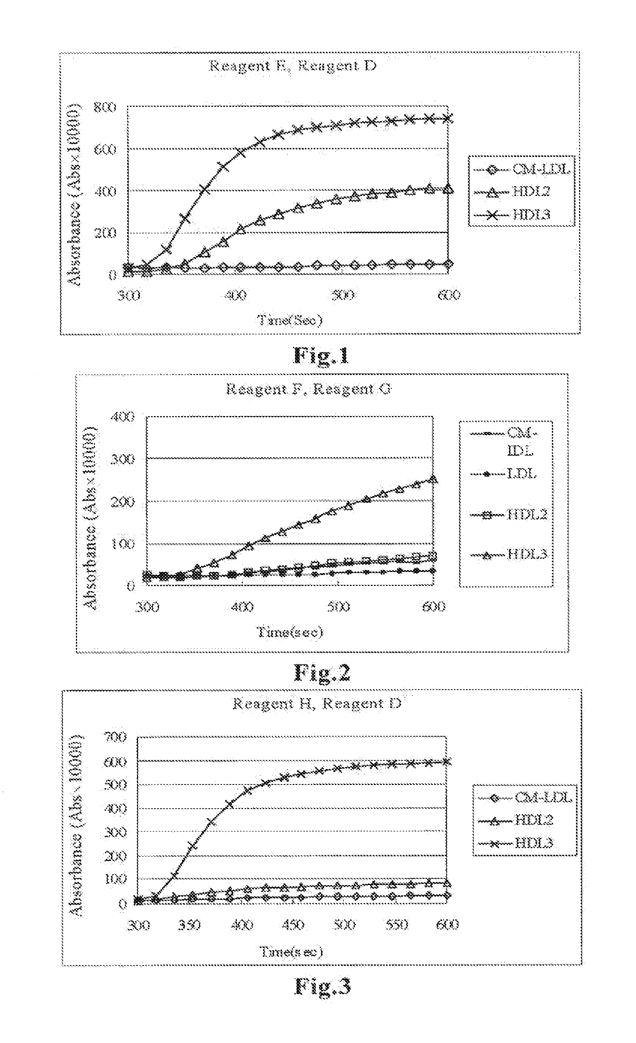
[0062]Fractionation by ultracentrifugation was carried out to obtain the CM-LDL fraction, HDL2 fraction and HDL3 fraction, and each fraction was reacted with Reagent E prepared by adding phospholipase D (PLDP) to Reagent A used in Reference Example 1. Reagent D described below was further added to the reaction solution to perform measurement. In the measurement, 150 μL of Reagent E was added to 2 μL of serum, and the reaction was allowed to proceed for 5 minutes with warming, followed by addition of Reagent D to the reaction solution and additional 5 minutes of reaction with warming. The absorbances at a main wavelength of 700 nm and a sub-wavelength of 600 nm were measured.

Reagent EBES buffer (pH 7.0)100mmol / LHDAOS0.7mmol / LCatalase600U / LCholesterol oxidase1.4U / mLCholesterol esterase0.8U / mLPhospholipase D5.0U / mL

Reagent DBES buffer (pH 6.6)100mmol / LSodium azide0.1%Emulgen B661.5%4-Aminoantipyrine4.0mmol / LPeroxidase2.4U / mL

[0063]FIG. 1 shows the result in terms of changes in the absorb...

example 2

[0064]Reagent F was prepared by adding a surfactant and sphingomyelinase to Reagent A used in Reference Example 1, and Reagent G was prepared for the step of measuring HDL3 in the product obtained by reaction with Reagent F. The compositions of these reagents were as shown below. Fractionation was carried out by ultracentrifugation to obtain the fraction from CM to IDL, LDL fraction, HDL2 fraction and HDL3 fraction, and the obtained fractions were subjected to measurement. The procedure for measurement with the reagents was the same as in Example 1. The absorbance was measured at each measurement time.

Reagent FBES buffer (pH 7.0)100mmol / LHDAOS0.7mmol / LPluronic F680.03w / v %Catalase600U / LCholesterol oxidase1.4U / mLCholesterol esterase0.8U / mLSphingomyelinase0.5U / mL

Reagent GBES buffer (pH 6.6)100mmol / LSodium azide0.1%Emulgen A902.0%4-Aminoantipyrine4.0mmol / LPeroxidase2.4U / mL

[0065]FIG. 2 shows the result in terms of changes in the absorbance with time of each fraction after addition of Re...


PUM

PropertyMeasurementUnit
densityaaaaaaaaaa
densityaaaaaaaaaa
reaction temperatureaaaaaaaaaa

Abstract

A method that enables quantification of cholesterol in high-density lipoprotein 3 (HDL3) in a test sample without requiring a laborious operation is disclosed. The method for quantifying cholesterol in HDL3 comprises: Step 1 wherein phospholipase and / or sphingomyelinase is / are allowed to act on a test sample to transfer cholesterol to the outside of the reaction system; and Step 2 wherein cholesterol remaining in the reaction system is quantified. The method enables specific quantification of HDL3 cholesterol in a test sample using an automatic analyzer without requirement of a laborious operation such as ultracentrifugation or pretreatment. Further, quantification of the HDL2 cholesterol level can also be carried out by subtracting the HDL3 cholesterol level from the total HDL cholesterol level obtained by a conventional method for quantifying the total HDL cholesterol in a test sample.

Description

CROSS REFERENCE TO RELATED APPLICATIONS[0001]This application is a Continuation of copending application Ser. No. 13 / 811,562, filed on Mar. 4, 2013, which was filed as PCT International Application No. PCT / JP2011 / 066672 on Jul. 22, 2011, which claims the benefit under 35 U.S.C. § 119(a) to Patent Application No. 2010-166317, filed in Japan on Jul. 23, 2010, all of which are hereby expressly incorporated by reference into the present application.TECHNICAL FIELD[0002]The present invention relates to a method for quantifying cholesterol in high-density lipoprotein 3 (which may be hereinafter referred to as “HDL3”) (cholesterol in HDL3 may be hereinafter referred to as “HDL3 cholesterol”).BACKGROUND ART[0003]Since high-density lipoprotein (HDL) receives cholesterol from various tissues including walls of blood vessels with arteriosclerosis, it is involved in the action of removal of cholesterol accumulated in cells. Therefore, HDL cholesterol is also called the reverse cholesterol trans...

Claims


Application Information

Patent Timeline
Patent Type & Authority Applications(United States)
IPC IPC(8): G01N33/92C12Q1/60C12Q1/44
CPCG01N33/92C12Q1/60C12Q1/44G01N2333/918G01N2405/08G01N2800/323G01N2405/04C12Q1/42G01N33/48
Inventor HIGUCHI, MAIKOITOH, YASUKI
Owner DENKA CO LTD
Learn More