
Photomask, method for producing photomask, and method for producing color filter using photomask

a technology of photomask and color filter, which is applied in the direction of photomechanical equipment, instruments, photomechanical treatment originals, etc., can solve the problems of increasing the problem of one-shot exposure type photomask, and increasing the cost of one-shot exposure processing methods, so as to achieve good uniform line width (dimension).

Inactive Publication Date: 2019-05-23
TOPPAN PRINTING CO LTD
View PDF0 Cites 0 Cited by
  • Summary
  • Abstract
  • Description
  • Claims
  • Application Information

AI Technical Summary

Benefits of technology

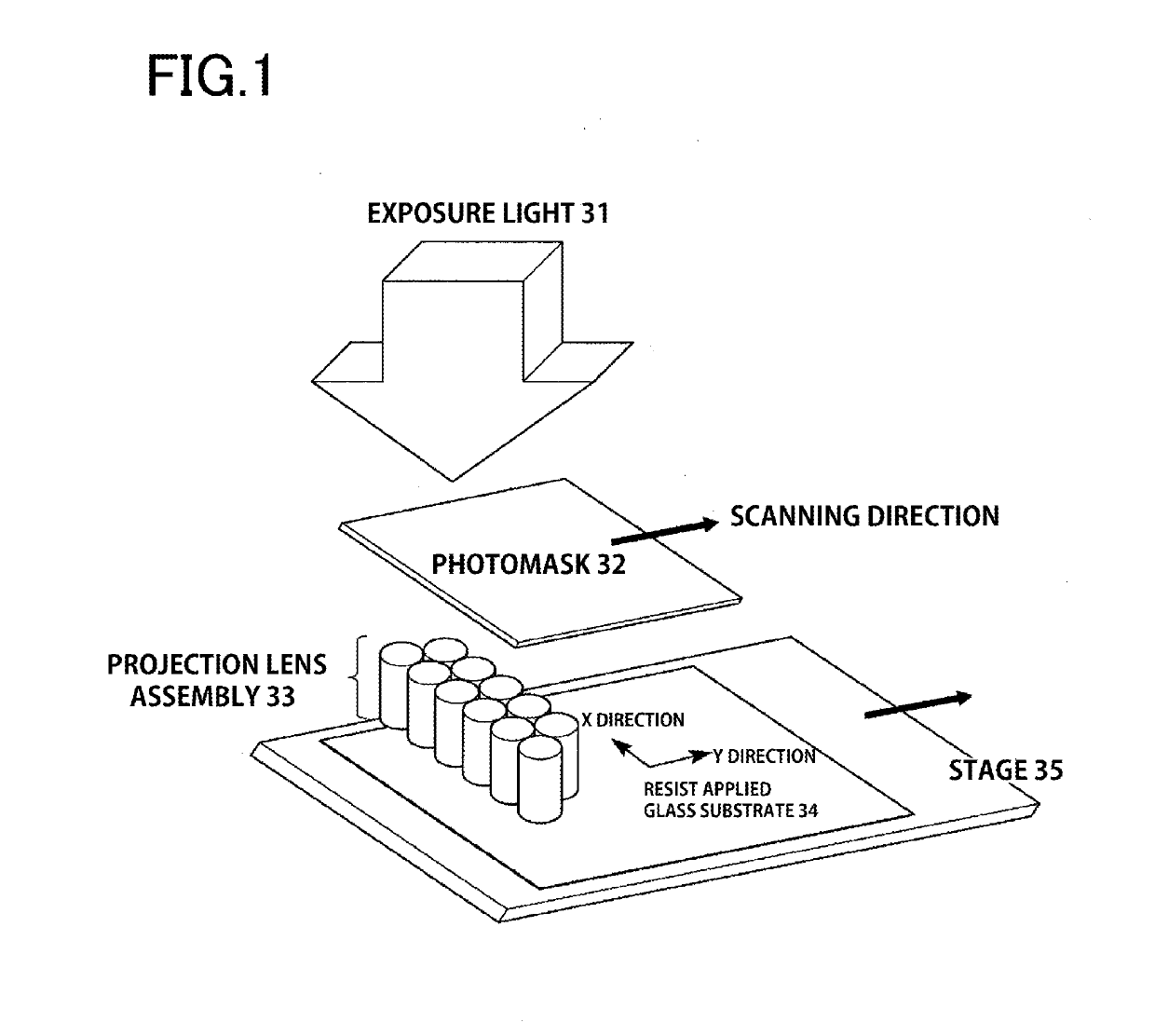
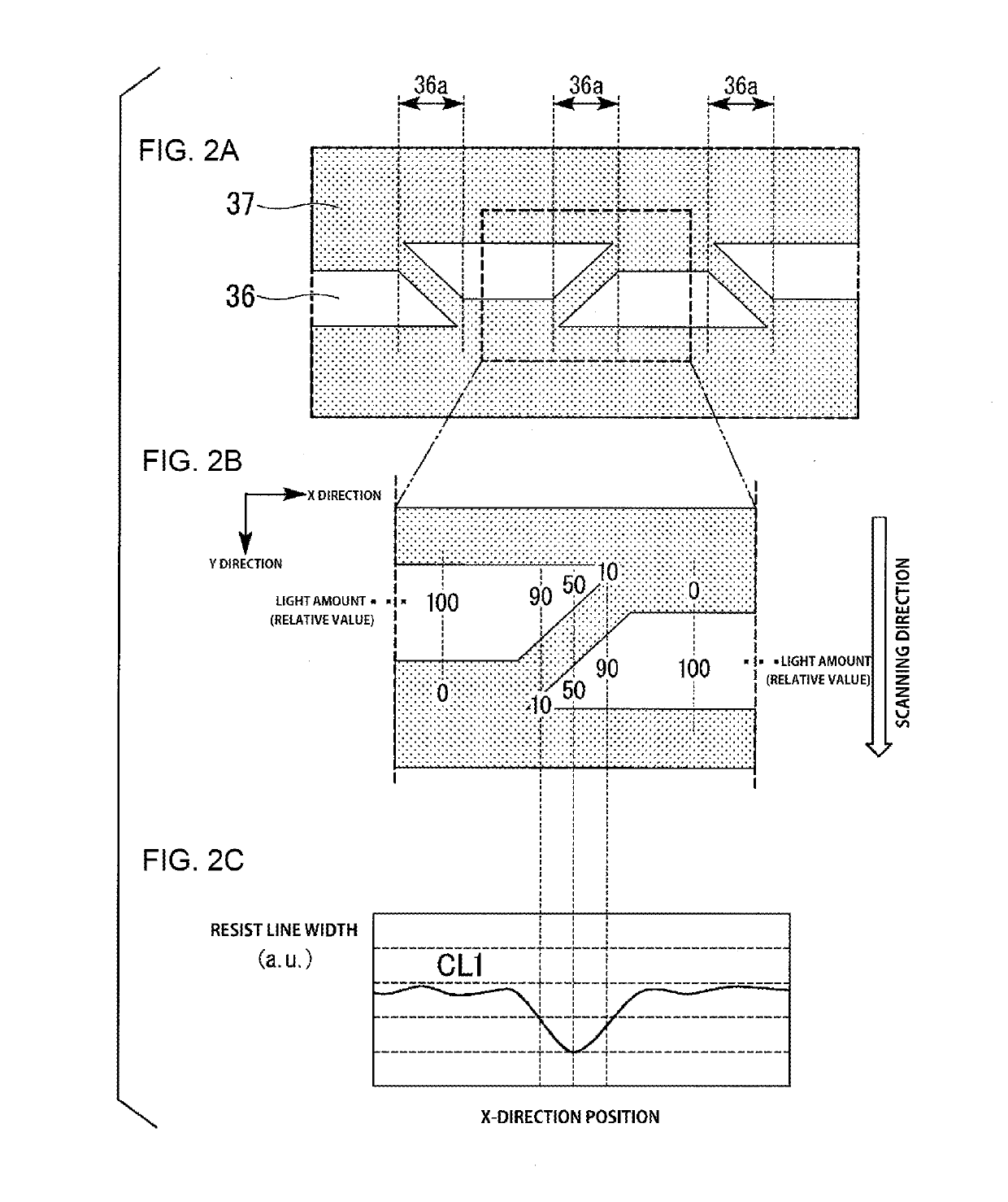
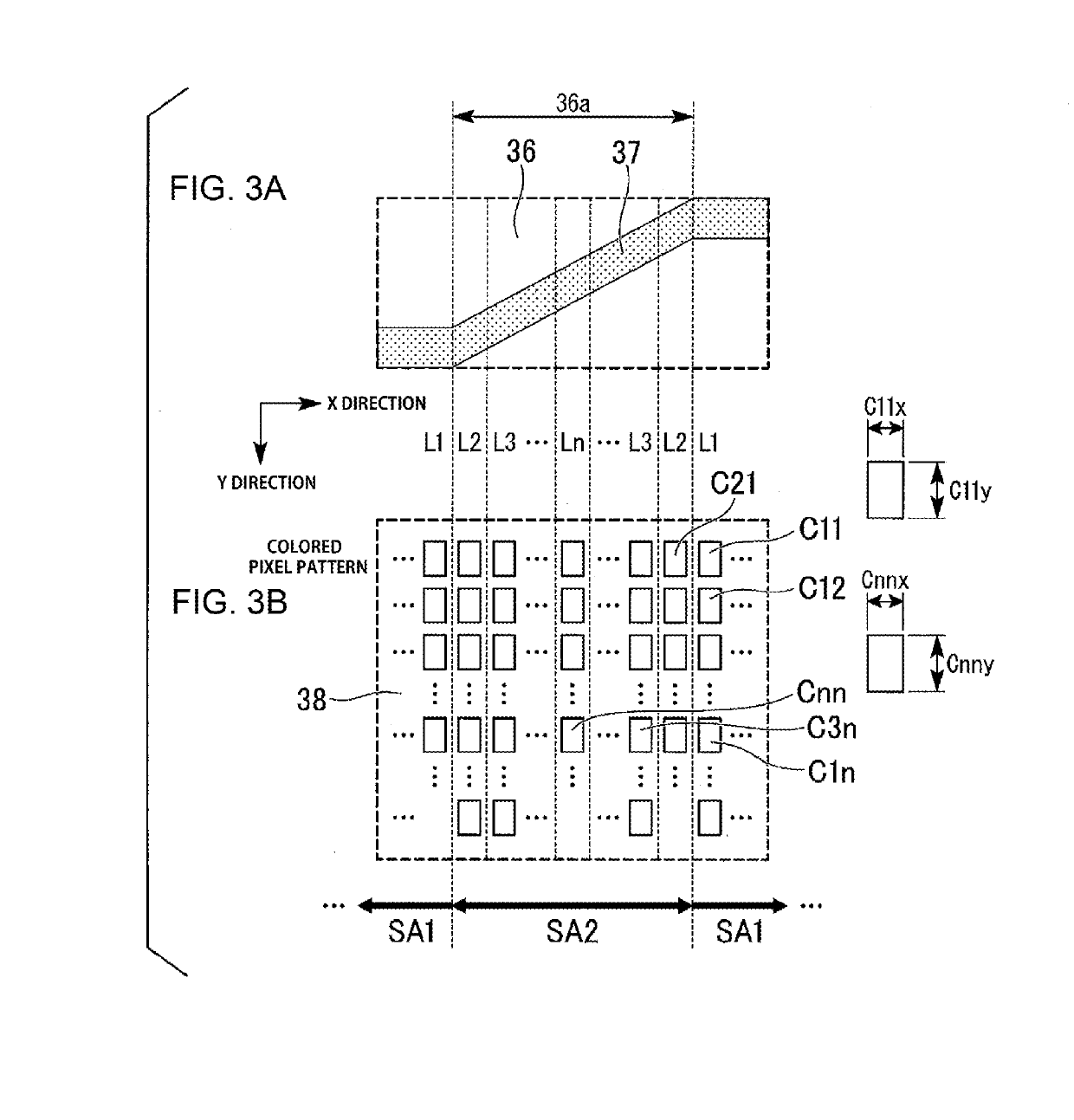
The present invention is related to a photomask for use in scanning type projection exposure. The technical effect of the invention is to improve or even solve problems related to the incorrect line width of patterns in the retransferred region caused by the presence of connecting portions in the lens assembly during scanning exposure. The invention corrects the line width of patterns in the retransferred region with patterns in the same region of the same photomask but without connecting portions.

Problems solved by technology

However, as the size of the photomask increases, which is caused by a further increase in substrate size, the technological problems of the one-shot exposure type photomask have increased, and has become expensive.
That is, such problems in the one-shot exposure processing method are increasing.

Method used


Image

  • Photomask, method for producing photomask, and method for producing color filter using photomask
  • Photomask, method for producing photomask, and method for producing color filter using photomask
  • Photomask, method for producing photomask, and method for producing color filter using photomask

Examples


first embodiment

[0053]With reference to the drawings, a description will now be given of a first embodiment of a photomask according to the present invention. The present invention is not limited to the following representative embodiments, and appropriate modifications can be made without departing from the spirit of the present invention. The representative embodiments described below are merely examples of the present invention, and the design thereof could be appropriately changed by one skilled in the art. The same constituent elements are denoted by the same reference numerals unless there is a reason for the sake of convenience, and redundant description is omitted. In the drawings referred to in the following description, for clarity, characteristic parts are enlarged, and thus the components are not shown to scale.

[0054]The photomask of the present invention can be applied to a method of producing a color filter substrate or a silicon substrate on which colored pixels or a black matrix are...

second embodiment

[0074]A description will now be given of a photomask according to a second embodiment of the present invention.

[0075]FIG. 9 is a schematic plan view showing an example of the photomask according to the second embodiment of the present invention. FIG. 10 is a schematic enlarged view showing a configuration of regions for single exposure of the photomask according to the second embodiment of the present invention. FIG. 11 is a schematic enlarged view showing a configuration of regions for combined exposure in the photomask according to the second embodiment of the present invention.

[0076]Because each drawing is a schematic diagram, the shape and dimensions may be enlarged (the same applies to the following drawings).

[0077]As shown in FIG. 9, the photomask 1 of the present embodiment is a mask for exposure used in the exposure apparatus which performs unmagnified exposure by using a plurality of projection optical systems. The photomask 1 includes a light transmitting substrate 2 and a...


PUM


Abstract

A photomask is used for scanning type projection exposure provided with a projection lens assembly composed of a lens assembly. A line width in a plurality of patterns of the photomask in a region to be transferred by performing scanning exposure including connecting portions of the lens assembly are corrected with respect to a line width of patterns which are the same as the patterns of the photomask present in a region to be transferred by performing scanning exposure but do not include the connecting portions.

Description

CROSS-REFERENCE TO RELATED PATENT APPLICATIONS[0001]This application is a continuation application filed under 35 U.S.C. § 111(a) claiming the benefit under 35 U.S.C. §§ 120 and 365(c) of International Patent Application No. PCT / JP2017 / 025967, filed on Jul. 18, 2017, which is based upon and claims the benefit of priority to Japanese Patent Application No. 2016-143333, filed on Jul. 21, 2016 and Japanese Patent Application No. 2016-238997, filed on Dec. 9, 2016; the disclosures of which are all incorporated herein by reference in their entireties.TECHNICAL FIELD[0002]The present invention relates to a photomask, a method for producing a photomask, and a method for producing a color filter using a photomask.BACKGROUND ART[0003]In recent years, the demand for liquid-crystal displays, particularly color liquid-crystal display panels, has remarkably increased with the increase in large-sized color televisions, laptop computers, and portable electronic devices. A color filter substrate us...

Claims


Application Information

Patent Timeline
IPC IPC(8): G03F1/70G02F1/1335G03F7/20G03F7/00G03F1/76
CPCG03F1/70G02F1/133516G02F1/133512G03F7/20G03F7/0007G03F1/76G02B5/201G03F1/00G02B5/20G03F7/2063G03F7/70258G03F7/70275G03F7/70958
Inventor OKUMURA, AKIHITOMIYAJI, HIROAKIYAMADA, TAKEHIRO
Owner TOPPAN PRINTING CO LTD
Learn More