Variable-speed magnetic coupling having radially movable magnet

a magnetic coupling and variable-speed technology, applied in the direction of magnets, dynamo-electric brakes/clutches, magnetic bodies, etc., can solve the problems of inability to adjust the speed according to the work needs of invention, the frequency converter has strict environmental requirements, and the problem of motor heating and even failure of ordinary magnetic couplings, etc. problems, to achieve the effect of reducing transmission component losses, effective solving the problem of heating or even failure, and efficient transmission

Active Publication Date: 2019-05-23
JIANGSU UNIV
View PDF0 Cites 13 Cited by
  • Summary
  • Abstract
  • Description
  • Claims
  • Application Information

AI Technical Summary

Benefits of technology

[0012]In the present disclosure, the driving disc is not in contact with the driven disc. The transmission of torques between two discs are achieved through the air gap magnetic field interaction, so as to avoid problems of generating restoring force and torque as well as vibration, etc. When the mechanical coupling is drove, and reduce transmission component losses. The disconnection of the load and the motor is achieved. By regulating the coupling area or air gap spacing between the permanent magnet and the conductor ring to change the air-gap magnetic density, not only the soft-start of the motor can be realized to effectively solve the problem of heating or even failure of the motor load start, but also efficient transmission can be achieved under different loads by regulating the position of the block.
[0013]When the present speed regulating mechanism is applied to a disc mechanism, a structure of one row of permanent magnet between the both sides of the conductor ring is used. It effectively uses the magnetic field on both sides of the permanent magnet and greatly enhances the utilization of permanent magnet. Unlike the previous patents, it adjusts the speed by regulating the coupling area between the permanent magnet and the conductor ring when the present speed regulating mechanism is applied to a disc mechanism, and the speed regulating mechanism can be widely used in magnetic couplers with the structures of disc, multi-disc, cylinder and wedge type. In addition, the driven disc adopts deep groove embedded conductor ring structure. The ability of torque transmission of the magnetic coupler has been greatly improved by the use of deep groove skin effect.
[0014]When a magnetic coupler is applied to a disc structure, the magnetic field generated by electromagnetic induction in the conductor ring and the interaction between the material of the driven disc (such as the yoke) and the permanent magnet cause a great attraction between the driving disc and the driven disc. It is especially difficult to adjust the axial spacing (that is, air gap spacing) between them. However, in the present invention, it is relatively easy to change their coupling area by radial displacement so that the mechanism is more reliable and practical.

Problems solved by technology

However, ordinary magnetic coupling does not solve the problem of motor heating and even failure when the load is started.
However, the frequency converter has strict requirements on the environment.
However, the invention cannot adjust the speed according to the work needs while the magnetic coupling operates, and is limited to be only applied in the cylinder mechanism.

Method used


Image

  • Variable-speed magnetic coupling having radially movable magnet
  • Variable-speed magnetic coupling having radially movable magnet
  • Variable-speed magnetic coupling having radially movable magnet

Examples


example 1

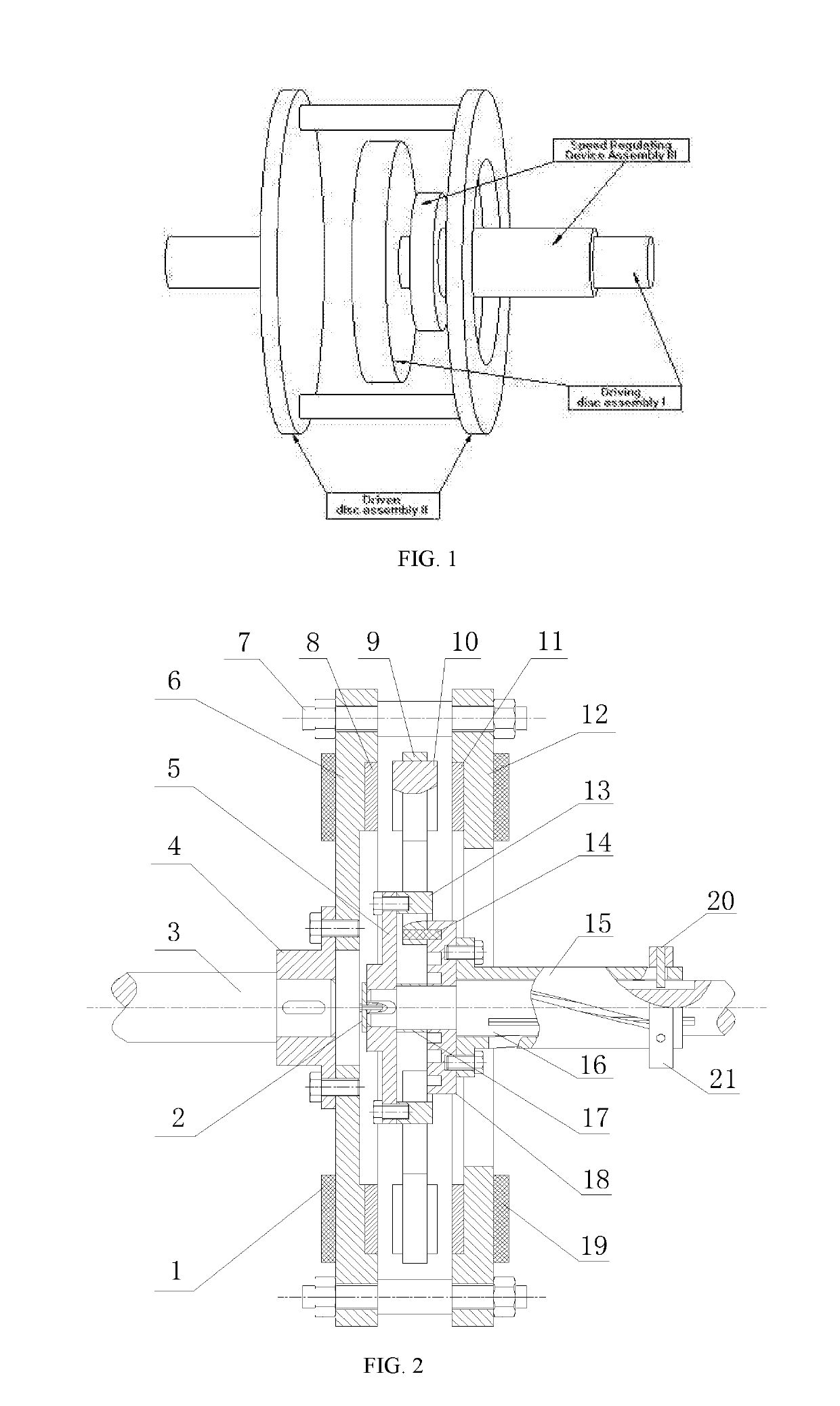
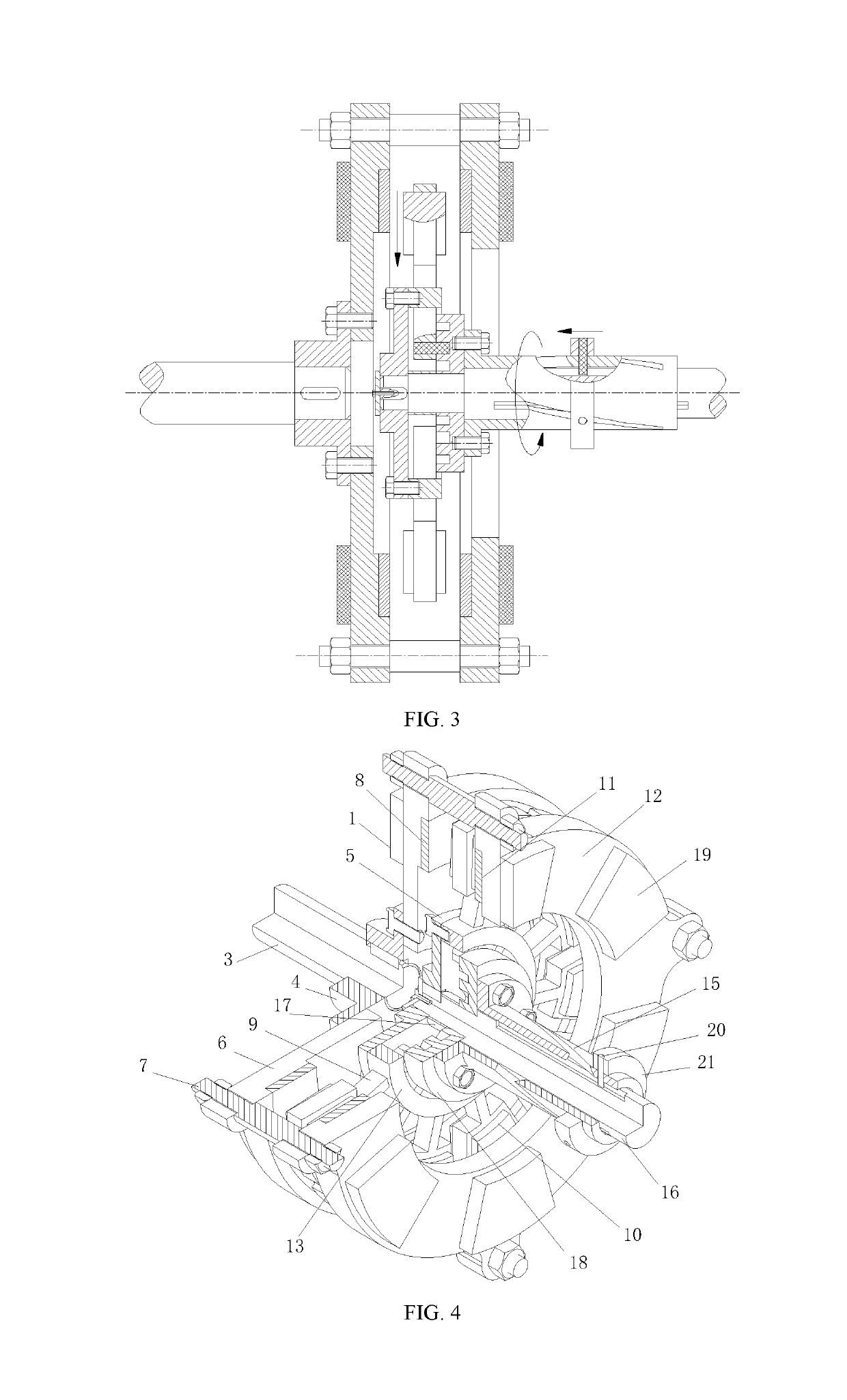
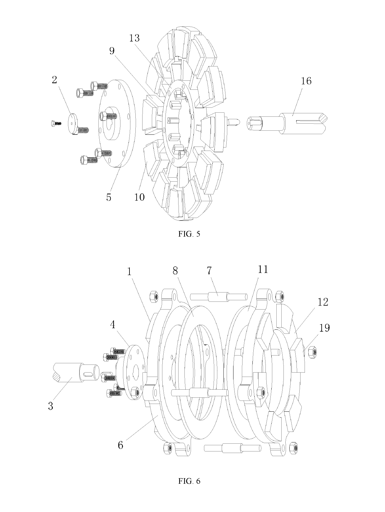
[0036]As shown in FIG. 1, it is composed of a driving disc assembly I, a driven disc assembly II and a speed regulating device assembly III. As shown in FIGS. 2, 4 and 5, the driving disc assembly includes a driving shaft 16, a driving shaft sleeve 5, a baffle 2, a round frame 13, a permanent magnet carrier 9, and a permanent magnet 10. A driving shaft sleeve 5 is connected to the left end of the driving shaft 16 by a key, and a baffle 2 is connected to the left end surface of the driving shaft 16 by screws to maintain the axial fixing of the driving shaft sleeve 5. A round frame 13 is connected to the right side of the driving shaft sleeve 5 by screws, and a rectangular through hole is formed in the round frame 13. A permanent magnet carrier 9 is inserted into the rectangular through hole of the round frame 13, and a permanent magnet 10 is bonded to the carrier frame of the permanent magnet carrier 9. As shown in FIG. 8, the permanent magnet 10 alternately arranged in N pole and S ...

example 2

[0041]As shown in FIG. 11, it is basically the same as example 1, except that a linear servo motor 23 is mounted on the block in this example, at the same time, rotational speed sensors are respectively mounted on the driving shaft and the driven shaft a limit sensor is installed at the corresponding positions of the left end and the right end of the speed regulating sleeve chute, and a temperature sensor is mounted on the heat sink, and an intelligent controller is additionally mounted. From the outside, the intelligent controller is composed of a controller casing 24, a graphic display unit 25, an operating keyboard unit 28, a sensor terminal 22, an output interface 26 and a communication interface 27, etc., As shown in FIG. 12, it is a block diagram showing the structural configuration and working principle of the intelligent controller, which is composed of an embedded microprocessor unit, a controller power supply and circuit unit, an operating keyboard unit, an graphic display...

example 3

[0044]As shown in FIG. 14, it is composed of a driving disc assembly, a driven disc assembly and a speed regulating device assembly. The driving disc assembly includes a driving shaft 46, a driving shaft sleeve 36, a baffle 32, a round frame 43, a permanent magnet carrier 37 and a permanent magnet 42. A driving shaft sleeve 36 is connected to the left end of the driving shaft 46 by a key, and a baffle 32 is connected to the left end surface of the driving shaft 46 by a screw to maintain axial fixing of the driving shaft sleeve 36. A round frame 43 is connected to the right side of the driving shaft sleeve 36 by a screw, and a rectangular through hole is formed in the round frame 43; a permanent magnet carrier 37 is inserted into the rectangular through hole of the round frame 43, The carrier frame at the upper end of the permanent magnet carrier 37 is a Y-shaped structure that cuts off the upper half, and a trapezoidal permanent magnet 42 is bonded to the Y-shaped carrier frame on t...


PUM

PropertyMeasurementUnit
humidityaaaaaaaaaa
temperatureaaaaaaaaaa

Abstract

A variable-speed magnetic coupling having a radially movable magnet, comprising a drive disc assembly (I), a driven disc assembly (II), and a speed adjusting device assembly (III). Relative rotation of a speed adjustment sleeve (15) with respect to a drive shaft (16) is achieved by means of contact and fitting of a cylindrical pin (20) with respect to a vertical recess on an inner wall of the drive shaft and to an inclined recess on an inner wall of the speed adjustment sleeve. The speed adjustment sleeve is connected to a circular slotted disc (18) by means of a screw. A permanent magnet (10) is attached to a permanent magnet bearer (9) and inserted into a rectangular through hole of a circular frame (13), and a radial movement of the permanent magnet is enabled by means of a cam and groove sliding block mechanism consisting of the circular slotted disc, the circular frame, the permanent magnet bearer, and the permanent magnet. By moving a movement block (21) to drive the movement pin (20) to slide in the recesses of the drive shaft and the speed adjustment sleeve and then drive the speed adjustment sleeve to rotate, the present invention enables a radial movement of the permanent magnet, and then changes a coupling area or an air gap distance between the permanent magnet and conductive rings (8, 11) on two sides, thus changing a magnetic flux density of the air gap, and accordingly enabling speed adjustment.

Description

FIELD OF THE INVENTION[0001]The invention relates to the field of transmission technology in mechanical engineering, and relates to a non-contact type magnetic induction coupling, in particular to a magnet radial movable adjustable speed magnetic coupling. It can be used between a large vibration motor and a load as a transmission system for power transmission and speed regulation.BACKGROUND OF THE INVENTION[0002]In the field of mechanical engineering, the coupling is an important part of the mechanical transmission system. It is called one of the three major components in the mechanical transmission. It is widely used in various fields of the machinery industry and is widely used in mining, metallurgy, aviation, weaponry, hydropower, chemical industry, textile and transportation sectors. Because the magnetic coupling is a non-contact connection, it can effectively solve the mechanical coupling's resilience and torque problems due to the axial deviation during installation, as well ...

Claims


Application Information

Patent Timeline
Patent Type & Authority Applications(United States)
IPC IPC(8): H02K49/10H02K51/00H01F7/02
CPCH02K49/102H02K51/00H01F7/0205H02K49/106H02K49/10H01F7/0242H02K21/023H02K2213/09
Inventor YANG, CHAOJUNLIU, KANGZHANG, WEIFENGWU, YINGZHILIU, MING
Owner JIANGSU UNIV
Why Eureka
Try Eureka