Supercharge Your Innovation With Domain-Expert AI Agents!

Transient voltage suppressor

Active Publication Date: 2019-05-30
UPI SEMICON CORP
View PDF7 Cites 1 Cited by
  • Summary
  • Abstract
  • Description
  • Claims
  • Application Information

AI Technical Summary

Benefits of technology

The invention is a transient voltage suppressor that can reduce the voltage spikes that occur during electrostatic discharge events. The suppressor has a simple structure and includes only an anode and a cathode. It includes a floating doped region and a heavily-doped region as a trigger structure, which can be adjusted to reduce the breakdown voltage. The suppressor has two current paths that can be activated simultaneously to prevent damage to the trigger structure. The overall resistance of the suppressor is reduced, and the majority of the current flows through the second current path to prevent damage to the trigger structure.

Problems solved by technology

Especially, because there are a lot of hot-swap interfaces in recent electronic products and the changes in consumer behavior, the risk of electrostatic discharge causing damage to electronic products becomes higher.
However, the structure of the conventional transient voltage suppressor is complicated, and the gate structure is required to control the turn-on voltage VON.
In addition, when an electrostatic discharge event occurs, the current in the conventional transient voltage suppressor is concentrated in the same current path causing the overall resistance of the transient voltage suppressor to be difficult to reduce.

Method used


Image

  • Transient voltage suppressor
  • Transient voltage suppressor
  • Transient voltage suppressor

Examples


Embodiment Construction

[0029]Exemplary embodiments of the present invention are referenced in detail now, and examples of the exemplary embodiments are illustrated in the drawings. Further, the same or similar reference numerals of the elements / components in the drawings and the detailed description of the invention are used on behalf of the same or similar parts.

[0030]A preferred embodiment of the present invention is a transient voltage suppressor. In this embodiment, the transient voltage suppressor is used to provide a protection function when an electrostatic discharge event occurs to ensure that the electronic component to be protected is not damaged by the electrostatic discharge, but is not limited thereto.

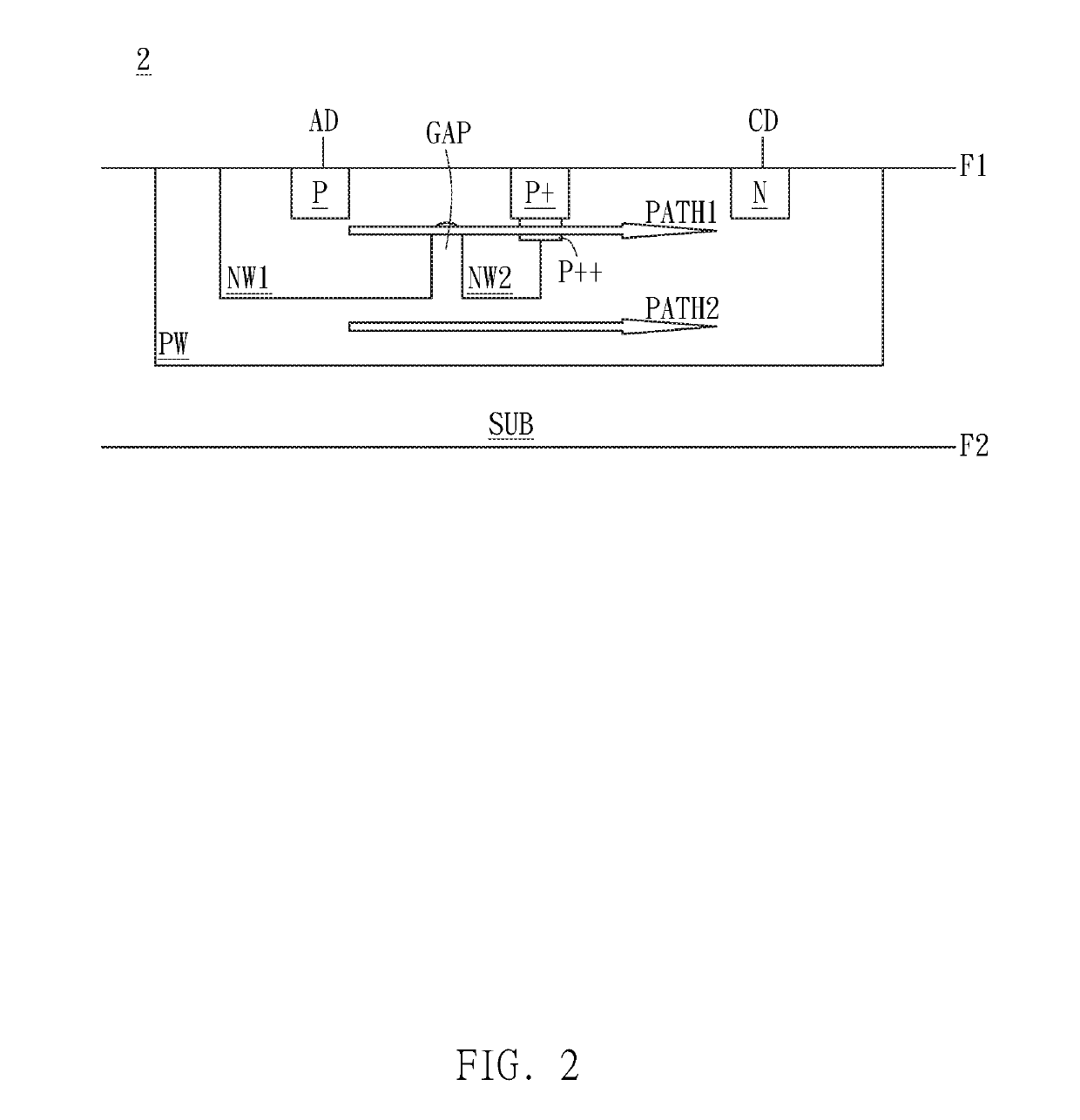
[0031]Please refer to FIG. 2. FIG. 2 illustrates a cross-sectional diagram of the transient voltage suppressor and the current shunting through the first current path and the second current path when an electrostatic discharge event occurs in a preferred embodiment of the invention.

[0032]As show...


PUM


Abstract

A transient voltage suppressor includes a substrate, a first well, a second well, a third well, a first electrode, a second electrode and a doped region. The first well is formed in the substrate and near a surface of the substrate. The second well is formed in the first well and near the surface. The third well is formed in the first well and near the surface. There is a gap between the second well and the third well. The first electrode and second electrode are formed in the second well and near the surface respectively. The first well and first electrode have a first electrical property. The second well, third well and second electrode have a second electrical property. The doped region is formed between the first electrode and second electrode and near the surface and electrically connected with the first well and third well.

Description

BACKGROUND OF THE INVENTION1. Field of the Invention[0001]The invention relates to transient voltage; in particular, to a transient voltage suppressor (TVS).2. Description of the Prior Art[0002]In general, electrostatic discharge is one of the important factors affecting the yield and reliability of electronic products. Especially, because there are a lot of hot-swap interfaces in recent electronic products and the changes in consumer behavior, the risk of electrostatic discharge causing damage to electronic products becomes higher. Therefore, many manufacturers have raised the electrostatic discharge test specifications to the highest level. Among the many electrostatic protector products, the transient voltage suppressor array (TVS array) has the advantages of fast conduction speed and low clamping voltage, and has become the best choice for meeting the highest level of electrostatic discharge test specifications.[0003]Please refer to FIG. 1. FIG. 1 illustrates a diagram showing c...

Claims


Application Information

Patent Timeline
IPC IPC(8): H01L29/06H01L27/02
CPCH01L29/0615H01L27/0248H01L27/0255H01L29/0619H01L27/0259H01L27/0262
Inventor CHEN, CHIH-HAO
Owner UPI SEMICON CORP
Features
  • R&D
  • Intellectual Property
  • Life Sciences
  • Materials
  • Tech Scout
  • Unparalleled Data Quality
  • Higher Quality Content
  • 60% Fewer Hallucinations
Learn More