Laser Additive Manufacturing Apparatus and Laser Additive Manufacturing Method

Active Publication Date: 2019-06-06
DMG MORI SEIKI CO LTD
View PDF0 Cites 0 Cited by
  • Summary
  • Abstract
  • Description
  • Claims
  • Application Information

AI Technical Summary

Benefits of technology

The patent aims to solve the problem of forming a uniform deposition in high quality and efficiency during continuous additive manufacturing using a laser beam with high energy density. The solution provided is a laser additive manufacturing apparatus and method that can achieve this goal.

Problems solved by technology

As a result, solidification cracking or the like may occur in a deposited portion.
Thus, continuous additive manufacturing with multiple back and forth scanning further increases a temperature difference between a central portion of a molten pool and a peripheral portion thereof.
This may cause a problem that a void or residual stress occurs to deteriorate quality.
Accordingly, it causes a problem that a size of the molten pool is changed, and a uniform deposition cannot be formed.

Method used


Image

  • Laser Additive Manufacturing Apparatus and Laser Additive Manufacturing Method
  • Laser Additive Manufacturing Apparatus and Laser Additive Manufacturing Method
  • Laser Additive Manufacturing Apparatus and Laser Additive Manufacturing Method

Examples


example

[0081]Next, the following simulation results will be described with referring to FIGS. 8A to 8C; (A) a temperature distribution in an irradiation region that is irradiated with a laser beam having a light intensity distribution of a Gaussian distribution and scanned; (B) a temperature distribution in an irradiation region that is irradiated with a laser beam having a light intensity distribution of a top-hat type and scanned; and (C) a temperature distribution in an irradiation region that is irradiated with a laser beam having a light intensity distribution of a dog-ear type and scanned as described in the embodiment above. FIGS. 8A to 8C illustrate temperature distributions in respective irradiation regions each of which is scanned with the corresponding one of laser beams having light intensity distributions of a Gaussian distribution, a top-hat type, and a dog-ear type. In each of the irradiation regions when being scanned, a darker-color portion has a higher temperature and a l...


PUM

PropertyMeasurementUnit
Fractionaaaaaaaaaa
Fractionaaaaaaaaaa
Light intensityaaaaaaaaaa

Abstract

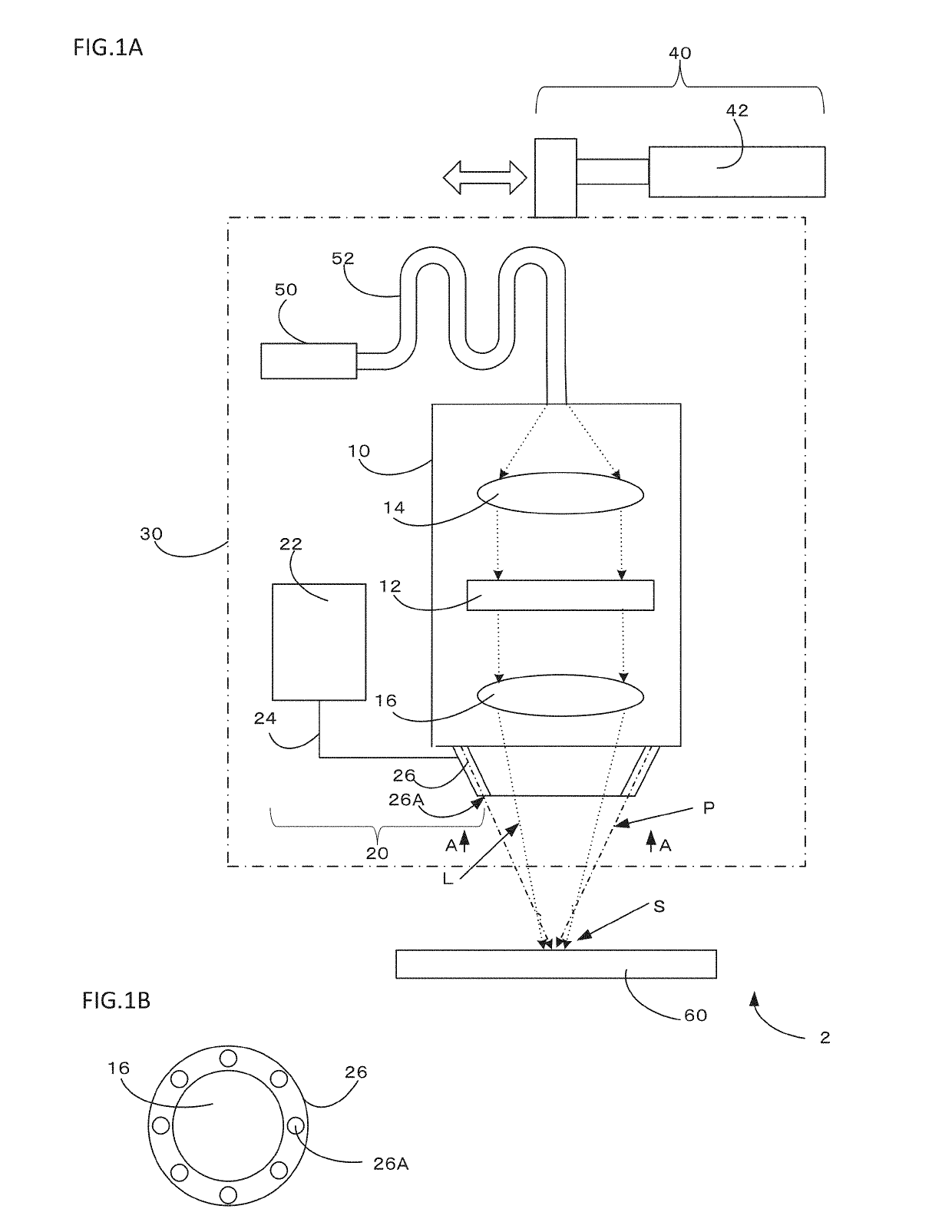
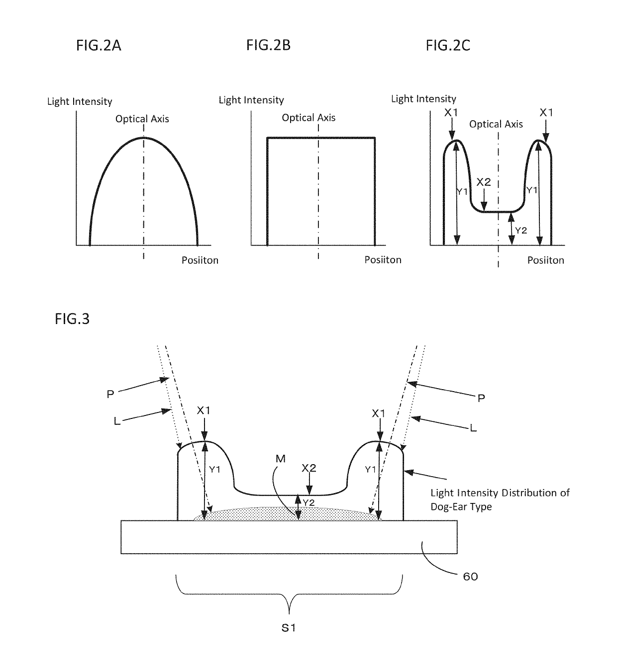
A laser additive manufacturing apparatus and a method thereof are provided. The apparatus includes an irradiation unit that irradiates an irradiation region with a laser beam having a light intensity distribution converted by a diffractive optical element, a head having a material supplying unit for supplying powder material to the irradiation region, and a movement mechanism which relatively moves the head and a workpiece. In the irradiation region, irradiation light forms a substantially circular spot having a light intensity distribution in which light intensity in an outer peripheral portion is higher than light intensity in a central portion, and the central portion has predetermined light intensity, and the material supplying unit supplies the powder material to the substantially circular spot.

Description

CROSS-REFERENCE TO RELATED APPLICATION[0001]This application claims priority to Japanese Patent Application No. 2017-232687 filed Dec. 4, 2017, the disclosure of which is hereby incorporated in its entirety by reference.BACKGROUNDTechnical Field[0002]The present disclosure relates to a laser additive manufacturing apparatus and a laser additive manufacturing method for forming a deposition on a workpiece by scanning a workpiece while supplying a laser beam and powder material.Related Art[0003]Laser additive manufacturing in which a workpiece is scanned while supplying a laser beam and powder material to form a deposition on the workpiece has gradually spread. At this time, a typical laser beam has light intensity with a Gaussian distribution in an irradiation region, so that a central portion of the laser beam has high energy intensity. This causes a molten pool formed when a material is melted with a laser beam to have nonuniform temperature distribution in which a central portion ...

Claims


Application Information

Patent Timeline
IPC IPC(8): B29C64/268G02B27/09G02B27/30G02B26/10
CPCB29C64/268G02B27/0944G02B27/30G02B27/0955G02B26/10B29C64/153B29C64/286B33Y30/00B33Y10/00Y02P10/25B22F12/49B22F12/224B22F10/25B22F12/44B22F12/53B22F10/32B22F10/00
Inventor KONDO, MASAKI
Owner DMG MORI SEIKI CO LTD
Why Eureka
Try Eureka