Transportable garment printing platen

a printing plate and garment technology, applied in printing, typewriters, textiles and papermaking, etc., can solve the problems of consuming a considerable amount of time in loading and unloading garments, requiring a more complex type of garment printing machine, etc., to facilitate rapid loading and unloading of hats, facilitate printing, and facilitate printing

Active Publication Date: 2019-06-06
MARTINEZ LEO JR
View PDF14 Cites 7 Cited by
  • Summary
  • Abstract
  • Description
  • Claims
  • Application Information

AI Technical Summary

Benefits of technology

[0017]Printing upon hats involves difficulties not encountered in printing upon other types of garments. This is because hats, by their nature, do not readily present flat surfaces upon which designs, logos and lettering can be easily printed. The present invention provides a transportable platen with a unique construction that facilitates printing upon both the forehead area and the bill or visor area of a hat.
[0018]The transportable platen of the invention that is particularly applicable to printing on hats employs a front panel wrap locking system. This allows the printing machine operator to tuck in and secure the hat atop the flat top surface of the print panel support plate in such a manner as to facilitate rapid loading and unloading of the hat. Moreover, the top of the bill of the hat is flattened so as to keep it out of the way of the printing mechanism of a conventional garment printing machine and also allow clear printing on it.

Problems solved by technology

When designs of a plurality of colors are to be applied, a more complex type of garment printing machine is required.
With conventional garment printing machines a considerable amount of time is consumed in loading and unloading garments from the printing platens that are attached to the garment printing machine arms.

Method used


Image

  • Transportable garment printing platen
  • Transportable garment printing platen
  • Transportable garment printing platen

Examples


Embodiment Construction

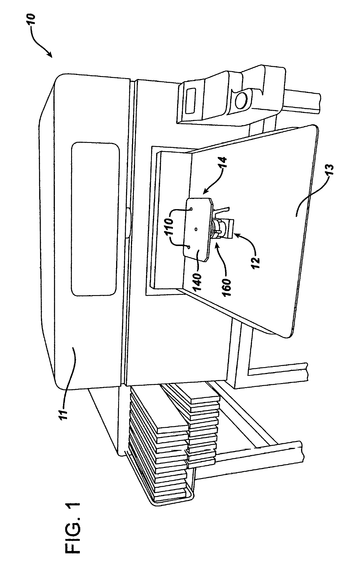
[0060]FIG. 1 illustrates a conventional digitized printing machine 10 having a horizontally extending garment receiving arm 12. A platen support 14 constructed according to the invention is mounted on the projecting end of the horizontally extending garment receiving arm 12. The garment receiving arm 12 extends outwardly away from the console of 11 of the garment printing machine 10 and resides above a work platform 13. The digitized printing machine 10 may, for example, be a Brothers GT3 81 machine, although the invention may be utilized with most commercially available digitized garment printing machines.

[0061]For purposes of reference throughout this specification, the directions fore and aft and longitudinal should be considered as parallel to the alignment of the garment receiving arm 12 on the printing machine 10, with forward referring to the direction toward the console of 11 and aft referring to the direction away from the console 11. Foreword also refers to the location cl...


PUM

PropertyMeasurementUnit
lengthaaaaaaaaaa
lengthaaaaaaaaaa
widthaaaaaaaaaa

Abstract

A garment printing machine is provided with a transportable platen that can be utilized to significantly decrease the delay in printing expended in loading and unloading a garment for printing in either a digitized garment printing machine or a screen garment printing machine. The platen is provided with structure that holds a print receiving area of a garment firmly in position atop a print panel support plate that forms a part of the platen. Furthermore, the invention includes a platen support structure that cooperates with the conventional couplings' on existing conventional garment printing machines. A plurality of transportable platens constructed according to the invention are utilized interchangeably so that while one garment loaded on one of the platens is being printed upon in the printing machine, the prior garment just printed upon is unloaded and the next garment to be printed is loaded onto another identical platen. This totally avoids any delay in printing due to loading and unloading of garments on the platens.

Description

BACKGROUND OF THE INVENTIONField of the Invention[0001]The present invention relates to an improvement in machines for printing images on a garments and an improved method of printing on garments. The improvement of the invention is applicable both to digital printing machines and manual screen printing machines.Description of the Prior Art[0002]Manual machines for printing images on garments, such as shirts, scarves, and pants have been in use for quite a number of years. In a simplified version where a design having a single color is to be imprinted, the machine has a single arm bearing a platen with a screen located above the platen. A garment, such as a shirt, is manually loaded onto the platen and positioned manually at a predetermined location on the platen. The screen is lowered onto the garment and ink is applied through the screen. The screen has a mask that allows ink to be transferred to the garment only at the unmasked location or locations. Once the ink has been applied...

Claims


Application Information

Patent Timeline
Patent Type & Authority Applications(United States)
IPC IPC(8): B41F15/18B41F15/08B41F15/10
CPCB41F15/18B41F15/0863B41F15/10B41F15/00B41F15/08B41F17/003B41F17/005B41J3/4078B41J11/02B41P2217/60D06P5/30
Inventor MARTINEZ, LEOMARTINEZ, JR., LEO
Owner MARTINEZ LEO JR
Why Eureka
Try Eureka