Neuromorphic system

a neuromorphic system and neuromorphic technology, applied in the field of neuromorphic systems, can solve the problems of increasing power consumption, increasing heat release problems, and affecting the development of the entire area, and achieve good extendability

Active Publication Date: 2019-06-06
SEOUL NAT UNIV R&DB FOUND
View PDF0 Cites 12 Cited by
  • Summary
  • Abstract
  • Description
  • Claims
  • Application Information

AI Technical Summary

Benefits of technology

[0033]In addition, since the neuromorphic system according to the invention can utilize the global self-controller in a case where an extended pulse generator and a v

Problems solved by technology

In recent years, many approaches have been made to imitate nervous systems of animals as power consumption has increased significantly and heat release problems have become more serious in integrated circuits based on the von Neumann architecture.
Accordingly, the CMOS-based neuron circuits in the related art have problems in that, due to a large size of

Method used


Image

  • Neuromorphic system
  • Neuromorphic system
  • Neuromorphic system

Examples


second embodiment

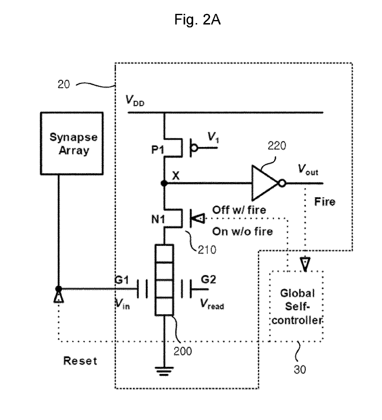
[0071]Hereinafter, the operation of the neuron circuit will be described.

[0072]When the current flows in the neuromorphic device to lower the potential of the node X, the potential of the output terminal is increased by the output circuit INV1, so that a current also flows in the second switch N2 to form a boosting path. As a result, the potential of the node X is more speedily lowered, and the firing occurs at a faster rate. The signal is transmitted to the p-MOSFET by the feedback circuit 230, and thus, P1 is turned on and the first switch N1 is turned off, so that the potential of the node X is increased to the voltage VDD again and the neuromorphic device is rest.

[0073]FIG. 4 is a circuit diagram of a neuron circuit according to a third embodiment of the invention. Referring to FIG. 4, a neuron circuit 24 according to the third embodiment is similar to the neuron circuit according to the second embodiment except that a third switch N3250 connected in series to the second switch...

third embodiment

[0075]Hereinafter, operations of the neuron circuit will be described. When the current flows in the neuromorphic device to lower the potential of the node X, the potential of the output terminal is increased by the output circuit INV1, so that a current also flows in the second switch N2 to form a boosting path. As a result, the potential of the node X is more speedily lowered, and the firing occurs at a faster rate. The p-MOSFET P1 is turned on by the feedback circuit, and at the same time, the third switch N3 is turned off to instantaneously prevent current from flowing in the second switch N2. The first switch N1 is turned off by the signal output from the global self-controller, the potential of the node X is stably increased to the voltage VDD again, and the neuromorphic device is reset.

first embodiment

[0076]FIG. 5 is a graph of voltage versus time illustrating operation characteristics of the neuron circuit in the neuromorphic system according to the invention.

[0077]Referring to FIG. 5, in the neuron circuit according to the invention, (a) illustrates a signal Vin input to the first gate electrode of the neuromorphic device as a signal pulse continuously output from the synapse array. (b) illustrates an output voltage Vout of the output circuit of the neuron circuit. When the signal pulse Vin from the synapse array is continuously input to the first gate electrode G1 of the neuromorphic device and the charges are accumulated and exceeds the predetermined threshold value, the voltage of the first gate electrode of the neuromorphic device is increased, and thus, the device operates as a positive feedback device, so that a current flows in the neuromorphic device and the potential of the node X is decreased. As a result, the voltage Vout of the output circuit is increased, and the f...


PUM


Abstract

Provided is a neuromorphic system using a neuron circuit. The neuromorphic system includes: one or two or more neuron circuits configured to output a firing signal according to signals input from a synapse array; a homeostatic circuit for each neuron circuit; and a global self-controller configured to generate and provide control signals for the neuron circuits by using the firing signal output from the neuron circuits. The neuron circuit includes a neuromorphic device and an output circuit that outputs the firing signal of the neuromorphic device. The global self-controller generates and supplies a reset signal to the neuromorphic device of the fired neuron circuit, and the global self-controller generates and supplies a lateral inhibition signal to the neuromorphic device of the non-fired neuron circuit. The homeostatic circuit alleviates inhibition of other neurons by the neurons with a predominant firing function.

Description

BACKGROUND OF THE INVENTION1. Field of the Invention[0001]The present invention relates to a neuromorphic system configured to be capable of implementing homeostasis, reset, and lateral inhibiting functions of a neuron by using neuron circuits including neuromorphic devices capable of imitating neurons at a low power and a high degree of integration in neuromorphic techniques.2. Description of the Related Art[0002]In recent years, many approaches have been made to imitate nervous systems of animals as power consumption has increased significantly and heat release problems have become more serious in integrated circuits based on the von Neumann architecture. Particularly, in the techniques imitating the nervous systems of animals, it is possible to improve the cognitive function and the determining function by enabling cognitive function and learning while greatly reducing power consumption.[0003]As a result, there is an opportunity to replace or greatly improve the functionality of ...

Claims


Application Information

Patent Timeline
IPC IPC(8): G06N3/063G06N3/04
CPCG06N3/0635G06N3/04G06N3/049G06N3/065G06N3/063H01L29/1033
Inventor LEE, JONG-HOWOO, SUNG YUNKANG, WON-MOOK
Owner SEOUL NAT UNIV R&DB FOUND
Why Eureka
Try Eureka