

Wireless power transmission apparatus and power transfer system
- Summary
- Abstract
- Description
- Claims
- Application Information
AI Technical Summary
Benefits of technology
Problems solved by technology
Method used
Image

Examples
first embodiment
Configuration of Power Transfer System
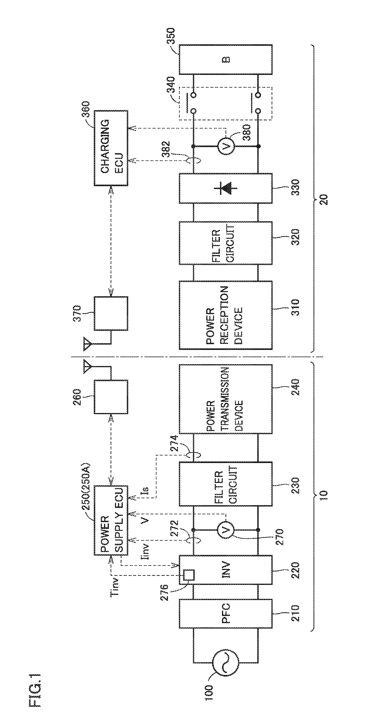
[0026]FIG. 1 is an overall configuration diagram of a power transfer system to which a wireless power transmission apparatus according to a first embodiment of the present disclosure is applied. Referring to FIG. 1, the power transfer system includes a power transmission apparatus 10 and a power reception apparatus 20. Power reception apparatus 20 is mounted on, for example, a vehicle or the like that can travel using electric power supplied from power transmission apparatus 10 and stored.
[0027]Power transmission apparatus 10 includes a power factor correction (PFC) circuit 210, an inverter 220, a filter circuit 230, and a power transmission device 240. Power transmission apparatus 10 further includes a power supply ECU (Electronic Control Unit) 250, a communication device 260, a voltage sensor 270, current sensors 272 and 274, and a temperature sensor 276.
[0028]PFC circuit 210 rectifies and boosts AC (alternate current) power received from an A...
second embodiment
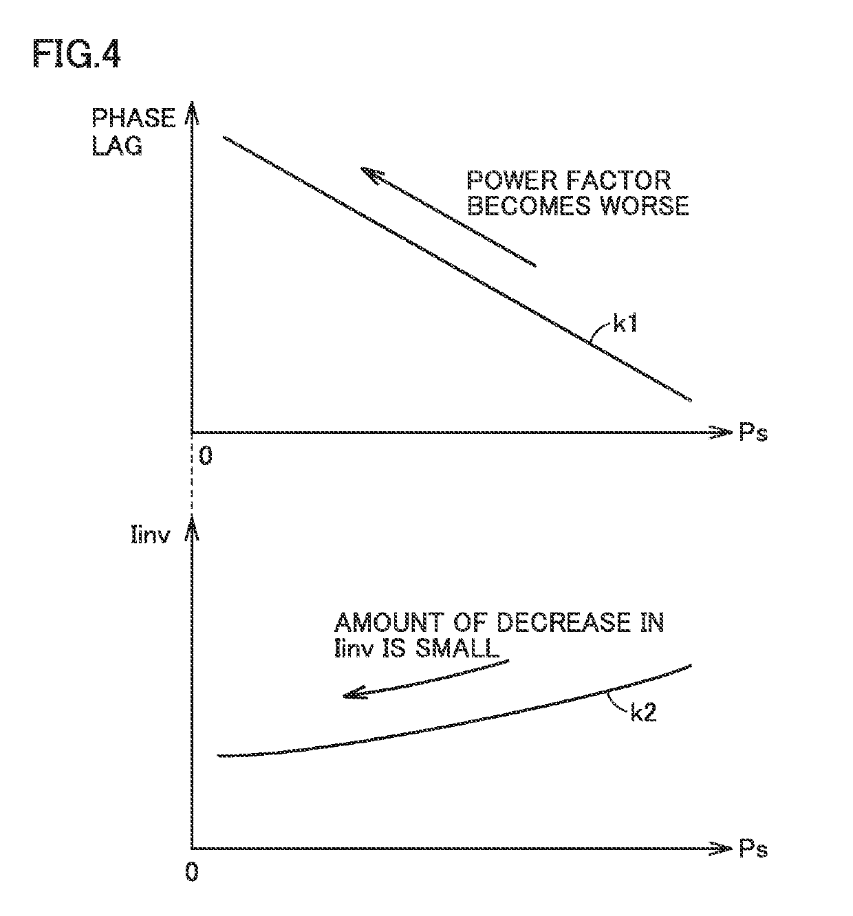
[0090]In the first embodiment, when temperature Tinv of inverter 220 exceeds limit temperature Tth, frequency f is adjusted such that current Iinv of inverter 220 decreases, while maintaining the magnitude of transmission power Ps.
[0091]In a second embodiment, when temperature Tinv exceeds limit temperature Tth, frequency f is adjusted such that the loss of inverter 220 decreases, while maintaining the magnitude of transmission power Ps. The loss of inverter 220 includes a loss caused by current Iinv flowing through inverter 220, and a loss caused by a recovery current flowing through the freewheeling diodes of inverter 220 due to a turn-on current of inverter 220. When the recovery current flows through the freewheeling diodes, heat generation in the freewheeling diodes increases and the loss of inverter 220 increases.
[0092]Accordingly, in the second embodiment, frequency f is adjusted such that the loss of inverter 220 decreases, with consideration given to the loss caused by the ...
PUM
 Abstract
Description
Claims
Application Information