Electrostatic transducer

a transducer and electrostatic technology, applied in the field of electrostatic transducers, can solve the problems of increasing the size of the whole actuator, the difficulty of making the electrode covered body having the electrode layer thinner, and the difficulty of adjusting the terminal to extract electricity from each electrode layer, etc., to achieve the effect of reducing the generation of large deformation force, high durability, and improving the durability of the first terminal electrode part and the second terminal electrode par

Inactive Publication Date: 2019-06-13
SUMITOMO RIKO CO LTD
View PDF0 Cites 2 Cited by
  • Summary
  • Abstract
  • Description
  • Claims
  • Application Information

AI Technical Summary

Benefits of technology

The patent describes a new design for an electrostatic transducer. In this design, the first terminal electrode part is laminated with the first extending part of the dielectric sheet, which is outside the electrostatic laminate but part of the dielectric sheet. This reduces the total thickness of the first terminal electrode part and the first extending part, which helps to prevent deformation near the boundary between the first terminal electrode part and the first counter electrode part. This design also eliminates the unnecessary parts of the dielectric sheet that do not contribute to the value of the electrostatic capacitance, improving the durability of the first and second terminal electrode parts. Overall, this design increases the durability and reliability of the electrostatic transducer.

Problems solved by technology

However, for the electrostatic actuator described in Japanese Laid-open No. 2014-150600, it is difficult to make the electrode covered body having the electrode layer thinner, and when a large number of electrode covered bodies are laminated, the size of the whole actuator increases.
In addition, when the thickness of the electrode layer is reduced, how to configure the terminal to extract electricity from each electrode layer also becomes a problem.
Particularly, because the electrode layer is thin, if the terminal is formed by extending the electrode layer, the durability of the electrode layer will be a problem.

Method used


Image

  • Electrostatic transducer
  • Electrostatic transducer
  • Electrostatic transducer

Examples


first embodiment

1. First Embodiment

(1-1. Outline of the Electrostatic Transducer 1)

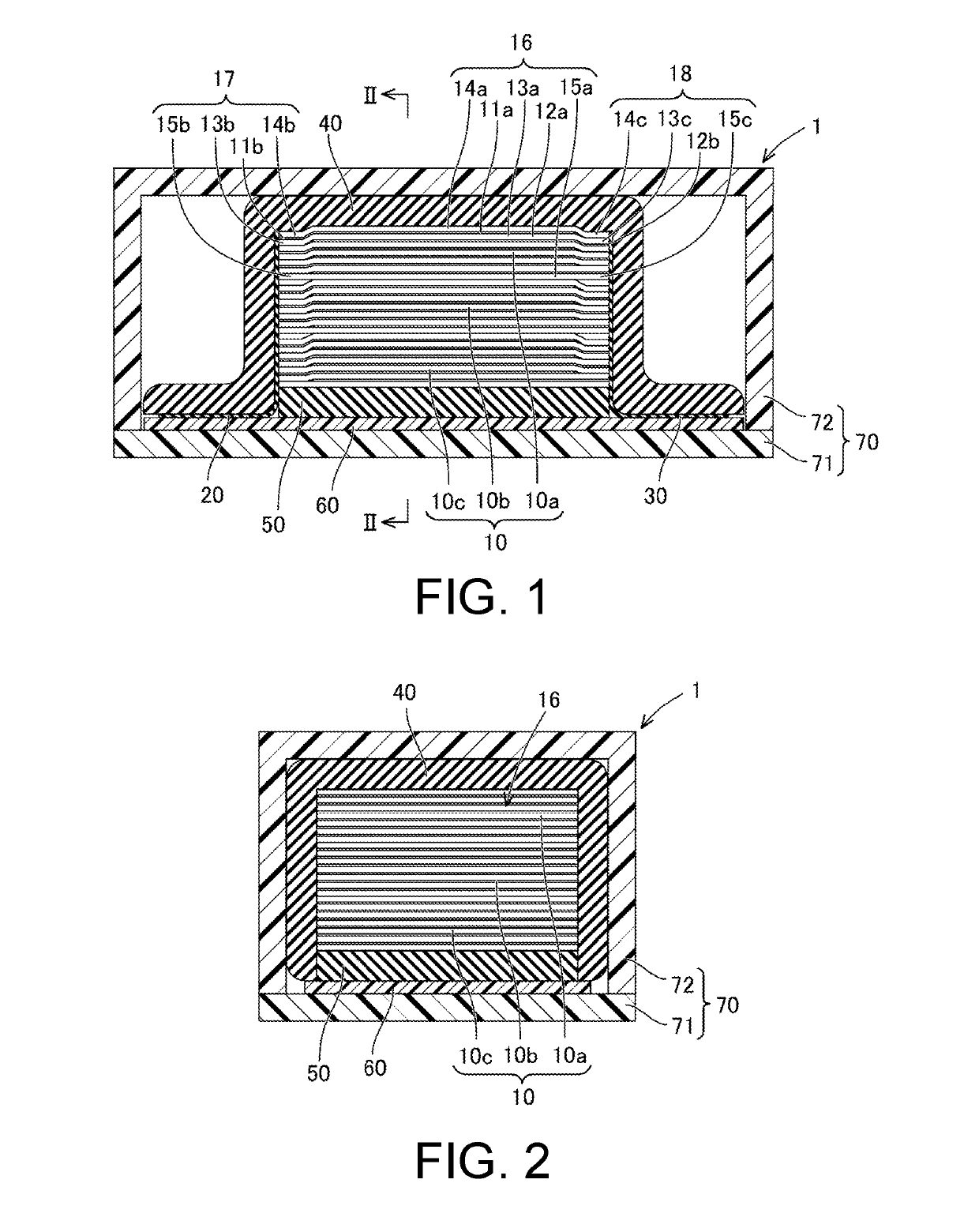
[0022]An electrostatic transducer 1 utilizes a change in electrostatic capacitance and is an actuator that generates vibration, sound, etc. or a sensor that detects vibration, sound, etc. The electrostatic transducer 1, which serves as an actuator, generates vibration by applying a voltage to an electrode. The electrostatic transducer 1, which serves as a sensor, generates a voltage at an electrode when the sensor vibrates due to input of vibration or sound.

[0023]The electrostatic transducer 1, which serves as a vibration actuator, is, for example, a device for presenting tactile vibration to a human being, a device for generating vibration in an opposite phase to a structure for damping the structure, or the like. The electrostatic transducer 1, which serves as an actuator for generating sound, is a speaker for generating sound waves to be sensed by hearing of a human being, a sound masking for cancelling noise, or ...

second embodiment

2. Second Embodiment

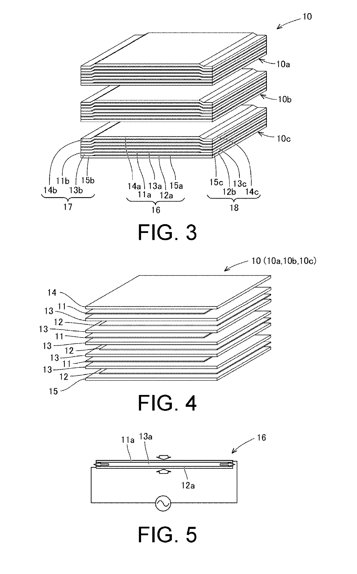
[0081]In the second embodiment, the outermost layer of the electrostatic laminate 16 is formed with an elastic modulus in the lamination direction larger than those of the other layers. The outermost layer of the electrostatic laminate 16 is the uppermost layer of the electrostatic unit 10a in FIG. 3 and the lowermost layer of the electrostatic unit 10c in FIG. 3. For example, by applying UV irradiation to surface-modify the uppermost layer of the electrostatic unit 10a, a nano-order cured layer is formed. Likewise, by applying

[0082]UV irradiation to surface-modify the lowermost layer of the electrostatic unit 10c, a nano-order cured layer is formed. A sheet having a desired elastic modulus may be disposed instead of applying UV irradiation. Therefore, when the vibration in the lamination direction of the electrostatic laminate 16 is transmitted to the cover 70, the transmission sensitivity of the vibration is improved.

third embodiment

3. Third Embodiment

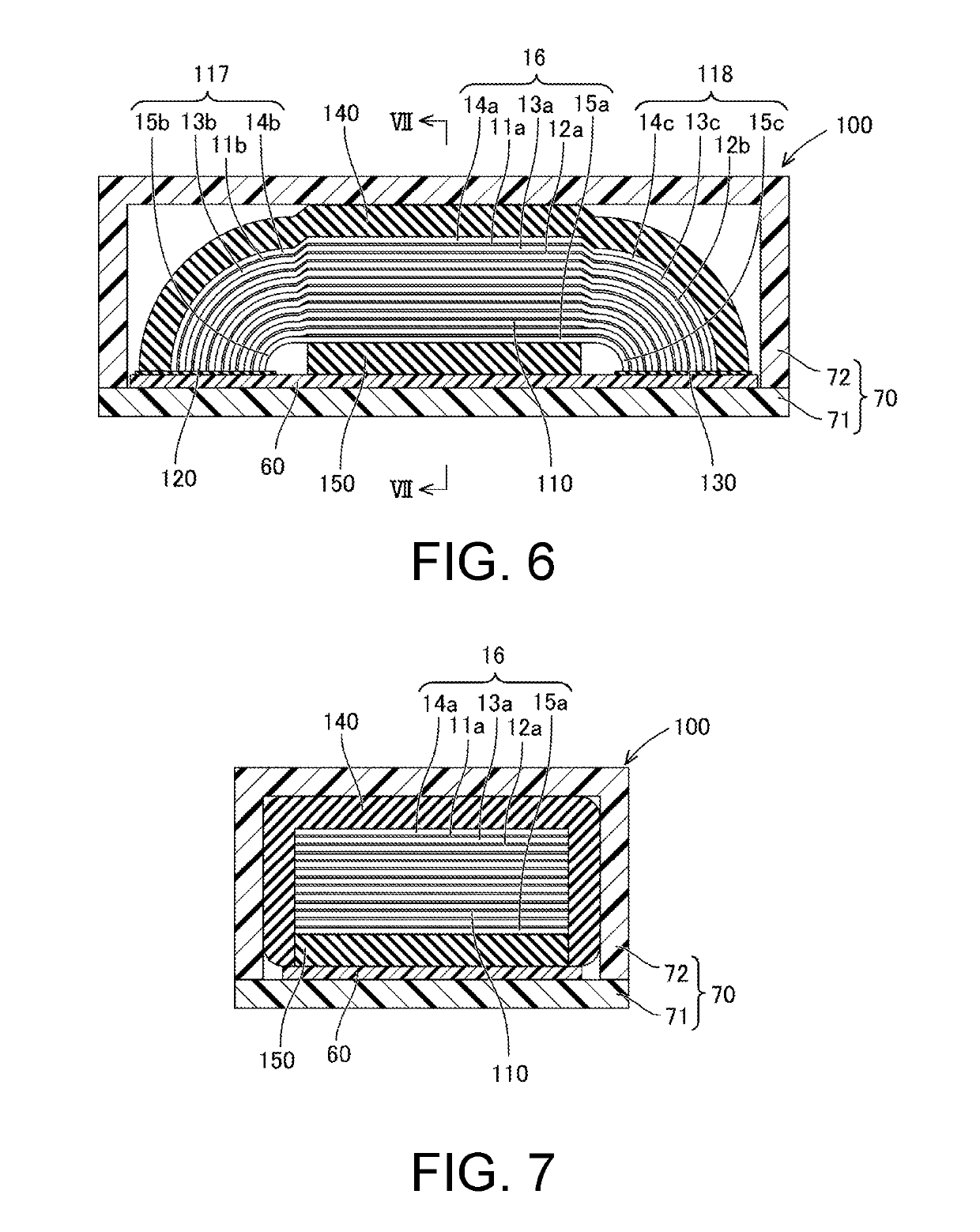
[0083]An electrostatic transducer 100 of the third embodiment will be described with reference to FIG. 6 and FIG. 7. In the electrostatic transducer 100, components the same as those of the electrostatic transducer 1 of the first embodiment are denoted by the same reference numerals, and description thereof is omitted.

[0084]The electrostatic transducer 100 includes an electrostatic unit 110, a first conductive part 120, a second conductive part 130, a first elastic body 140, a second elastic body 150, a control substrate 60, and a cover 70.

[0085]The electrostatic unit 110 includes an electrostatic laminate 16, a first terminal 117, and a second terminal 118. The electrostatic laminate 16 is formed in a planar shape. The electrostatic laminate 16 is formed by a first counter electrode part 11a, a second counter electrode part 12a, and a dielectric main body 13a. In other words, the first counter electrode part 11a, the second counter electrode part 12a, and the die...


PUM


Abstract

Provided is an electrostatic transducer which is small in size and has a large electrostatic capacitance, while having a durable constituent part of a conduction path, said constituent part being connected to an electrode. This electrostatic transducer is provided with a plurality of first electrode sheets, a plurality of second electrode sheets and a plurality of dielectric sheets. Each one of the plurality of first electrode sheets is provided with a first counter electrode part and a first terminal electrode part. Each one of the plurality of second electrode sheets is provided with a second counter electrode part and a second terminal electrode part. Each one of the plurality of dielectric sheets is provided with a dielectric main body, a first extending part that is interposed between a plurality of first terminal electrode parts, and a second extending part that is interposed between a plurality of second terminal electrode parts.

Description

CROSS-REFERENCE TO RELATED APPLICATIONS[0001]This application is a continuation application of International Application number PCT / JP2017 / 034129, filed on Sep. 21, 2017, which claims the priority benefit of Japan Patent Application No. 2016-213852, filed on Oct. 31, 2016. The entirety of each of the above-mentioned patent applications is hereby incorporated by reference herein and made a part of this specification.BACKGROUNDTechnical Field[0002]The disclosure relates to an electrostatic transducer.Description of Related Art[0003]An electrostatic transducer utilizes a change in electrostatic capacitance and is an actuator that generates vibration, sound, etc. or a sensor that detects vibration, sound, etc. Japanese Laid-open No. 2014-150600 describes an actuator in which a plurality of electrode covered bodies are alternately shifted layer by layer and laminated, which prevents creeping discharge between the electrodes. Besides, the electrode layer constituting each electrode covere...

Claims


Application Information

Patent Timeline
IPC IPC(8): H01L41/047H04R19/02B06B1/02
CPCH01L41/0472H04R19/02B06B1/0292H01L41/0477H04R19/04H10N30/872H10N30/877
Inventor NAKANO, KATSUHIKONASU, MASAKIMURASE, TAKANORI
Owner SUMITOMO RIKO CO LTD
Why Eureka
Try Eureka