Stiffener for an aircraft assembly

a technology for aircraft and stabilizers, which is applied in the direction of fuselage, fuselage bulkheads, fuselage frames, etc., can solve the problems of complex assembly, high cost, and time-consuming process of assembling the numerous clips, cleats and stabilizers, so as to reduce the weight of the stiffener assembly for a desired stiffness, the effect of lateral stability

Active Publication Date: 2019-06-27
AIRBUS SAS +1
View PDF0 Cites 3 Cited by
  • Summary
  • Abstract
  • Description
  • Claims
  • Application Information

AI Technical Summary

Benefits of technology

[0006]Beneficially, stability in the normal direction; that is along a longitudinal axis of the stiffener, is provided by the planar web portion, and further stability is provided in another direction by the corrugated web portion. With this arrangement, stiffness of the stiffener is provided in the normal, lateral and transverse directions is provided and as such the need for auxiliary clips, cleats, and stabilisers is minimised or removed. Furthermore, the weight of the stiffener assembly for a desired stiffness may be minimised.
[0007]The corrugation may extend transverse to a longitudinal axis of the planar web portion. As such, further lateral stability is provided.
[0009]With this arrangement, a desired stiffness may be provided along the length of the web. The complexity of manufacturing the stiffener may be minimised.

Problems solved by technology

The use of numerous parts including clips, cleats and stabilisers leads to a complex assembly.
As such, the complexity of their form involve significant costs.
Assembling the numerous clips, cleats and stabilisers is a complex and time consuming process.

Method used


Image

  • Stiffener for an aircraft assembly
  • Stiffener for an aircraft assembly
  • Stiffener for an aircraft assembly

Examples


Embodiment Construction

)

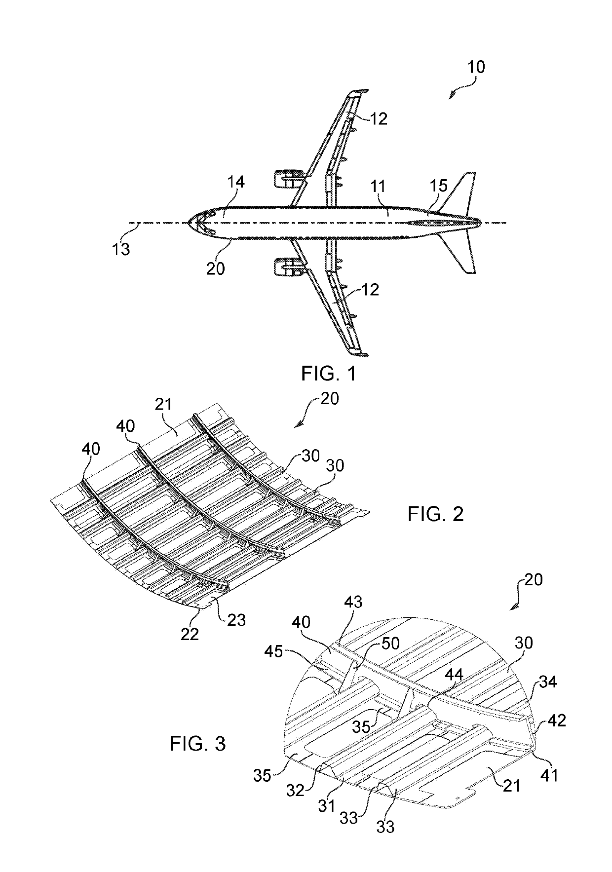
[0044]An aircraft 10 is shown in FIG. 1. The aircraft 10 includes a fuselage 11. Two wings 12 extend from the fuselage 11. It will be appreciated that the fuselage 11 and wings 12 may take a variety of different plan formed shapes and profiles depending on the particular application. The fuselage 11 defines a longitudinal axis 13. The longitudinal axis 13 extends from a forward end 14 to a rearward end 15. Each wing 12 comprises a wing box. The wing box forms the main body of the wing 12.

[0045]In the following description, the term “front” refers to components towards the leading edge of the wing, and the term “rear” refers to components towards the trailing edge of the wing. The terms “forward” and “rearward” shall be construed accordingly. The position of features may be construed relative to other components, for example a forward component may be disposed on a forward side of another component, but towards the rear of the wing.

[0046]The fuselage 11 comprises a fuselage structur...


PUM


Abstract

A stiffener for an aircraft assembly is disclosed. The stiffener provides structural stability to the aircraft assembly. The stiffener has a first stiffener part having a planar web portion and a second stiffener part arranged with the first stiffener part. The second stiffener part includes a corrugated web portion having a corrugation. The present application also relates to an aircraft assembly, a fuselage for an aircraft, an aircraft and a method of forming a stiffener for an aircraft assembly.

Description

FIELD OF THE INVENTION[0001]The present invention relates to a stiffener to an aircraft assembly. In particular, the present invention relates to a stiffener for providing structural stability to an aircraft assembly The present invention also relates to an aircraft assembly, a fuselage for an aircraft, an aircraft and a method of forming a stiffener for an aircraft assembly.BACKGROUND OF THE INVENTION[0002]Fuselage structures for an aircraft comprise a panel, acting as a fuselage skin, stringers extending longitudinally along the fuselage and stiffeners or frames extending perpendicular to the stringers. The stringers and stiffeners are fixed to the skin to provide structural support. The frames are typically C-shape, L-shape or Z-shape hoop profiles.[0003]The stiffeners are typically either integral stiffeners or frames; that is the frames are fixed to the skin, or differential stiffeners or frames; that is the frames are fixed in a spaced relationship to the skin. With differenti...

Claims


Application Information

Patent Timeline
Patent Type & Authority Applications(United States)
IPC IPC(8): B64C1/06
CPCB64C1/061B64C1/064B64C2001/0072B64C1/068B64C1/12B64C1/069B64C1/06
Inventor YADAV, AVNIASH KUMARRAMACHANDRA PATIL, VINAYAKWERNER, SVEN HARDY
Owner AIRBUS SAS
Why Eureka
Try Eureka