Combustion gas particle adhesion prevention boiler and method

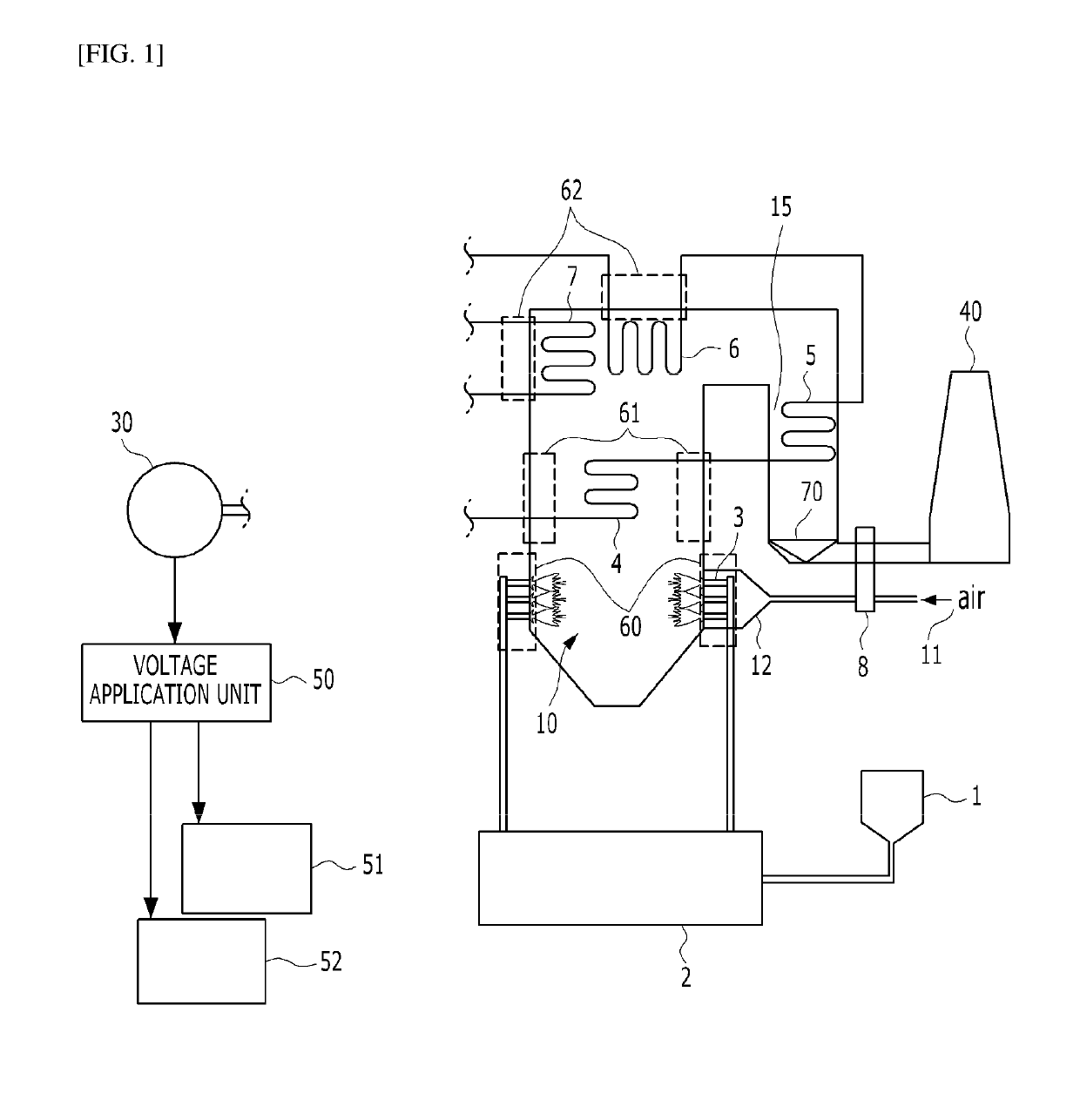
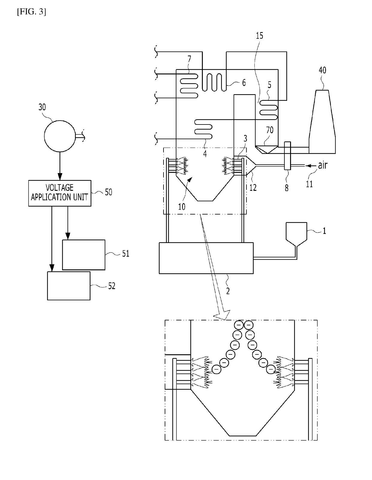
a combustion gas and adhesion prevention technology, which is applied in the field of combustion gas particle adhesion prevention boiler and method, can solve the problems of not only the adhesion of combustion gas particles to the tube, the inability to deliver heat energy to the fluid contained in the tube, and the inconvenience of using a device for generating wind, such as a soot blower, so as to achieve the effect of convenient collection

Active Publication Date: 2019-06-27
DOOSAN HEAVY IND & CONSTR CO LTD
View PDF0 Cites 1 Cited by
  • Summary
  • Abstract
  • Description
  • Claims
  • Application Information

AI Technical Summary

Benefits of technology

[0020]The present disclosure can apply a negative voltage to the combustion unit for combusting fuel to negatively charge the combustion gas particles generated through the combustion, and apply a positive voltage to the dust collector for collecting the combustion gas particles, such that the negatively charged combustion gas particles are easily collected in the dust collector by the attractive force with the positively charged dust collector.
[0021]The present disclosure can apply a negative voltage to the combustion unit for combusting fuel to negatively charge the combustion gas particles generated through the combustion, and apply a negative voltage to the tube through which fluid flows, such that the negatively charged combustion gas particles are not adhered to the tube by the repulsive force with the negatively charged tube.
[0022]The present disclosure can apply a negative voltage to the combustion unit for combusting fuel to negatively charge the combustion gas particles generated through the combustion, and apply a negative voltage to the inner wall of the furnace, such that the negatively charged combustion gas particles are not adhered to the inner wall of the furnace by the repulsive force with the negatively charged inner wall of the furnace.

Problems solved by technology

When the combustion gas particles are adhered to the tube, it is difficult for the heat energy to be delivered to the fluid contained in the tube, such that the temperature inside the boiler should be increased for the delivery.
In addition, there is an inconvenience in using a device for generating wind, such as a soot blower, in order to remove the combustion gas particles adhered to the tube.
In addition, there is an inconvenience that the combustion gas particles are adhered not only to the tube, but also to the inner wall of the furnace, such that the adhered combustion gas particles should be removed.

Method used


Image

  • Combustion gas particle adhesion prevention boiler and method
  • Combustion gas particle adhesion prevention boiler and method
  • Combustion gas particle adhesion prevention boiler and method

Examples


Embodiment Construction

[0032]The foregoing and further aspects are embodied through the embodiments described with reference to the accompanying drawings. It is to be understood that the components of each embodiment are capable of various combinations within the embodiments as long as they are not mutually exclusive or mutually contradictory. In addition, the present disclosure can be implemented in many various forms and is not limited to the embodiments described herein.

[0033]In order to clearly explain the disclosure illustrated in the drawings, parts not related to the description are omitted, and like parts are denoted by similar reference numerals throughout the specification. Then, it will be understood that when an element is referred to as “comprising” another element, the element is intended not to exclude other elements, but to further include other elements unless the context clearly indicates otherwise.

[0034]The term “unit” described in the specification refers to a block configured to chang...


PUM


Abstract

A combustion gas particle adhesion prevention boiler includes a furnace for containing a combustion gas and passing an exhaust gas; a dust collector for collecting combustion gas particles present in the exhaust gas; a combustion unit for combusting fuel and injecting a flame generated by the combustion into the furnace in order to generate the combustion gas; and a voltage application unit for negatively charging the fuel. The combustion gas particle adhesion prevention boiler, and a method using the same, prevent combustion gas particles generated by the combustion of fuel from being adhered to a tube, the inner wall of a furnace, etc., by applying a negative voltage to the combustion unit, and applying a positive voltage to a dust collector, such that the negatively charged combustion gas particles can be easily collected in the dust collector by the attractive force with the positively charged dust collector.

Description

CROSS-REFERENCE TO RELATED APPLICATIONS[0001]This application claims priority to Korean Patent Application No. 10-2017-0177475, filed on Dec. 21, 2017, which is incorporated herein by reference in its entirety.BACKGROUND OF THE DISCLOSUREField of the Disclosure[0002]The present disclosure relates to a combustion gas particle adhesion prevention boiler and method, and more particularly, to a combustion gas particle adhesion prevention boiler and method, which prevent combustion gas particles generated by the combustion of fuel from being adhered to a tube, the inner wall of a furnace, etc.Description of Related Art[0003]Generally, a power plant is an apparatus that converts fuel energy into electrical energy, and is largely composed of a boiler, a turbine, and a generator. The boiler is a device for heating water to generate vapor. Then, the turbine is rotated by the vapor generated through the boiler, and the generator generates electrical energy based on the rotation of the turbine...

Claims


Application Information

Patent Timeline
Patent Type & Authority Applications(United States)
IPC IPC(8): F23J15/02F23C99/00F23L15/04
CPCF23J15/022F23C99/001F23L15/04Y02E20/34F22B37/107F23J15/025F28F19/004F23J2217/102
Inventor NA, SANG GUN
Owner DOOSAN HEAVY IND & CONSTR CO LTD
Why Eureka
Try Eureka