Eureka AIR delivers breakthrough ideas for toughest innovation challenges, trusted by R&D personnel around the world.

Inductor component

a technology of components and components, applied in the manufacture of coils, basic electric elements, inductances, etc., can solve the problems of low yield rate, reduced possibility, and defects such as cracking and so on between the insulating layer and the coil conductor layer, and achieve the effect of low yield ra

Pending Publication Date: 2019-06-27
MURATA MFG CO LTD
View PDF0 Cites 3 Cited by
  • Summary
  • Abstract
  • Description
  • Claims
  • Application Information

AI Technical Summary

Benefits of technology

The patent text describes a way to make an inductor component that has fewer internal defects, which can lower the yield rate. The method involves using a coil conductor layer that contains sulfur and multiple insulating layers. This configuration reduces the likelihood of delamination and cracking between the layers. Overall, this patent is about how to make a better inductor component that is more reliable and efficient.

Problems solved by technology

In the production of the above-described inductor component, internal defects such as delamination, cracking and so on between the insulating layer and the coil conductor layer may occur.
This may result in a low yield rate.
Furthermore, when the inductor component is mounted on the circuit board, the magnetic flux is substantially parallel to the main surface of the circuit board and is unlikely to be blocked by the circuit wiring on the circuit board.
This configuration reduces the possibility that the magnetic flux passing through the outer side of the coil conductor layer is blocked by the external conductor layer.

Method used


Image

  • Inductor component
  • Inductor component
  • Inductor component

Examples


Embodiment Construction

[0022]Hereinafter, one aspect of this disclosure is described as an embodiment.

[0023]In the attached drawings, some of the components are illustrated in magnified scale for ease of understanding. The dimension ratio of the components may be different from the actual dimensions or may differ from one figure to another.

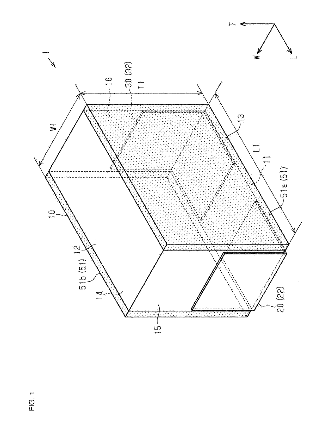
[0024]As illustrated in FIG. 1, an inductor component 1 includes an element body 10. The element body 10 has a substantially cuboidal shape. Herein, the “cuboidal shape” includes a cuboidal shape having chamfered corners or chamfered edges and a cuboidal shape having rounded corners or rounded edge. In addition, the “cuboidal shape” may have a corrugated section, for example, over an entire or a portion of a main surface or a side surface. Opposing surfaces of the “cuboidal shape” may be imperfectly parallel to each other and may be slightly tilted with respect to each other.

[0025]The element body 10 has a mounting surface 11. The mounting surface 11 faces a circuit boa...


PUM

PropertyMeasurementUnit
length L1aaaaaaaaaa
length L1aaaaaaaaaa
length L1aaaaaaaaaa

Abstract

An inductor component includes an element body including insulating layers laminated on one another, and a coil conductor layer winding on a main surface of one of the insulating layers. The coil conductor layer contains sulfur.

Description

CROSS-REFERENCE TO RELATED APPLICATION[0001]This application claims benefit of priority to Japanese Patent Application No. 2017-245301, filed Dec. 21, 2017, the entire content of which is incorporated herein by reference.BACKGROUNDTechnical Field[0002]The present disclosure relates to an inductor component.Background Art[0003]Hitherto, electronic components are mounted in various electronic devices. One of the electronic components is a multilayer inductor component as described, for example, in Japanese Patent No. 5821535. A multilayer inductor component includes an element body including laminated multiple insulating layers and coil conductor layers winding on the main surfaces of the insulating layers.SUMMARY[0004]In the production of the above-described inductor component, internal defects such as delamination, cracking and so on between the insulating layer and the coil conductor layer may occur. This may result in a low yield rate.[0005]Accordingly, the present disclosure prov...

Claims


Application Information

Patent Timeline
Patent Type & Authority Applications(United States)
IPC IPC(8): H01F27/28H01F27/29H01F41/04
CPCH01F27/2804H01F27/292H01F41/043H01F2027/2809H01F17/0013
Inventor MIYOSHI, HIROMIKONDO, KENTANAKASHIMA, YASUNARI
Owner MURATA MFG CO LTD
Why Eureka
Eureka Blog
Learn More