
Device for anchoring and protecting self-service terminals and vaults in general

a self-service terminal and vault technology, applied in the direction of machine frames, special foundation layouts, constructions, etc., can solve the problems of increasing time-consuming and difficult to breach the protective layers of self-service terminal vaults, being able to avoid criminal raids, and improving consumer market appeal.

Active Publication Date: 2019-07-04
TECH BANCARIA SA
View PDF6 Cites 6 Cited by
  • Summary
  • Abstract
  • Description
  • Claims
  • Application Information

AI Technical Summary

Benefits of technology

The inventor created a device that helps protect self-service terminals and vaults from theft. The device is designed to be durable and resistant to damage, even from backhoe loaders. This makes it a valuable addition to the bank safety equipment market.

Problems solved by technology

Currently, considering that each self-service terminal has a chance of containing significant amounts, said self-service terminals are being raided by criminals in many ways.
However, nowadays, due to some anti-theft devices being developed and installed inside said self-service terminals, some raiding methods are no longer used, as the protective layers of the vaults of self-service terminals are increasingly harder and time-consuming to breach, including smoke and paint generation devices, among others, that draw large attention from passersby.
Current securing systems for these self-service terminals—ATMs, for the most part, cannot withstand criminal raids using backhoe loaders due to several factors, among which are excessive force applied to anchoring bolts that are eventually broken due to shearing or exceeding the tensile strength of said bolts.
Another factor that undermines the retaining strength of the ATM terminal is sandy soil, which prevents proper grip of the anchoring kit that is bolted to the ground.
Finally, its rigid assembly renders bolts more susceptible to impacts to which the equipment is subjected during a raid, and subsequent break.

Method used


Image

  • Device for anchoring and protecting self-service terminals and vaults in general
  • Device for anchoring and protecting self-service terminals and vaults in general
  • Device for anchoring and protecting self-service terminals and vaults in general

Examples


Embodiment Construction

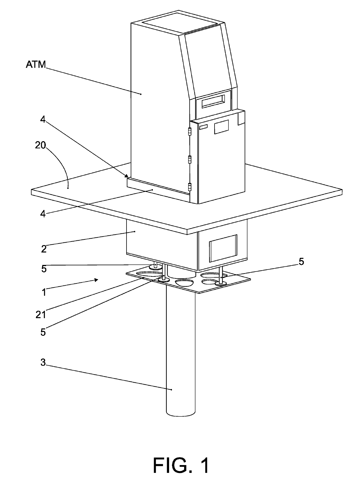
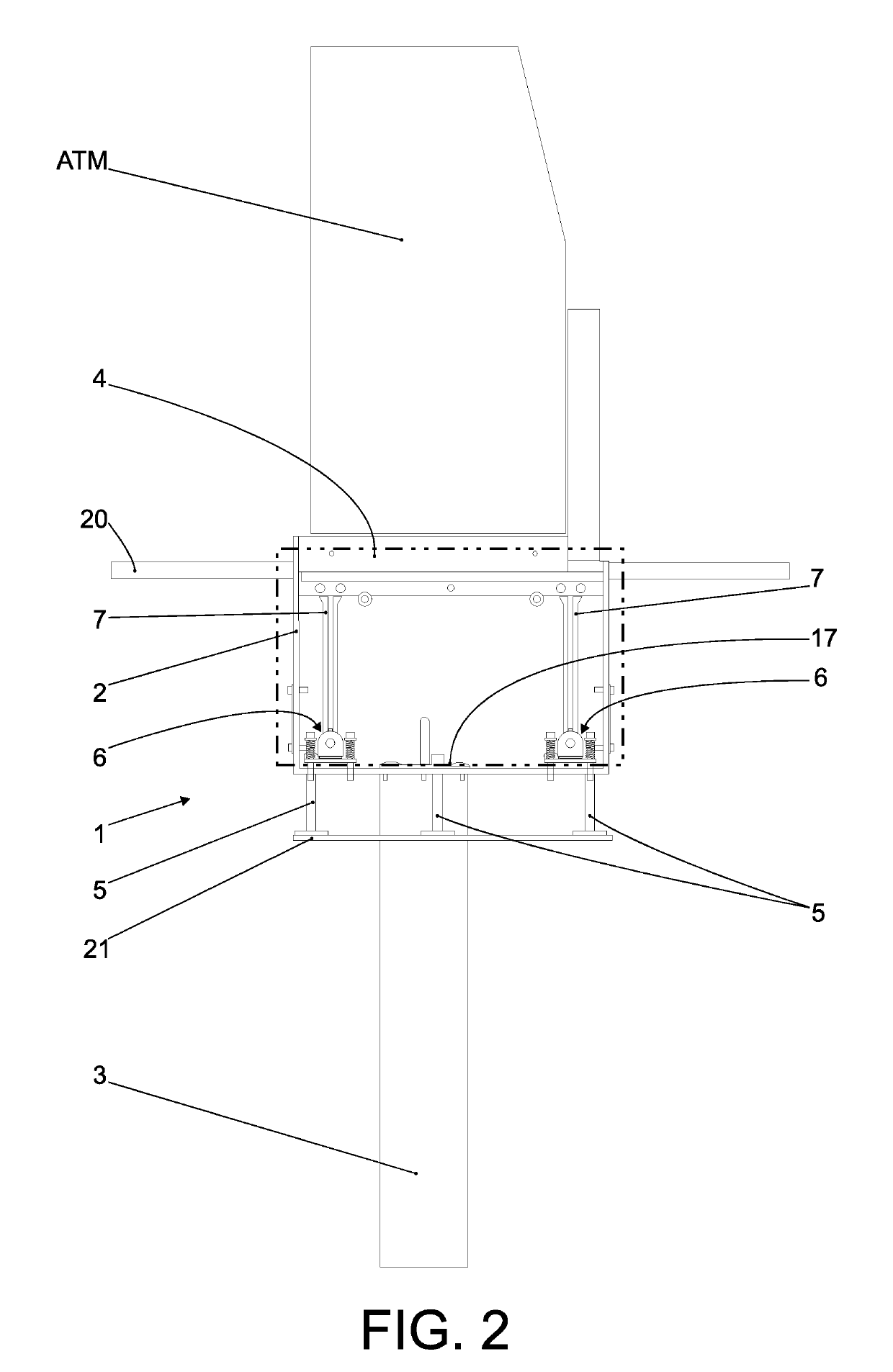
[0025]In agreement with the information provided by the figures above, this invention “DEVICE FOR ANCHORING AND PROTECTING SELF-SERVICE TERMINALS AND VAULTS IN GENERAL”, represented by reference number 1, features an anchoring structure defined by a box 2 manufactured in metallic material and a vertical and centrally positioned lower column 3 made of pre-cast concrete, and the only part of the structure of the box 2 placed above the ground are the outer vertical walls 4, which are placed 100 mm above the ground, while the rest is placed below the ground level.

[0026]Therefore, the device 1 is assembled immediately below the ATM terminal which, as previously said, comprises a box 2 which is supported against a central cylindrical column 3, with said box 2 including a protrusion corresponding to the protrusion of said ATM terminal.

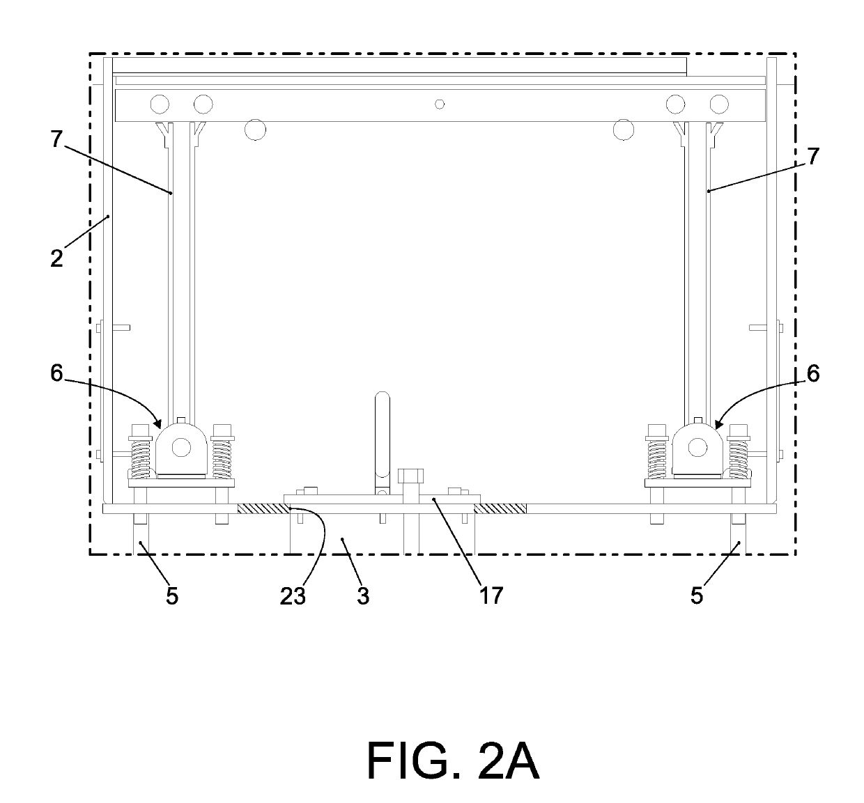
[0027]The box 2 is manufactured from metal panels, preferably carbon steel panels, below which a laminate support panel 21 is placed, partially vented and no...


PUM


Abstract

“DEVICE FOR ANCHORING AND PROTECTING SELF-SERVICE TERMINALS AND VAULTS IN GENERAL”, developed for application on self-service bank terminals (ATMs), as well as cash dispensing equipment, ATM recyclers, recycler vaults and general vaults, as defense against frequent theft in which the equipment is fully displaced using backhoe loaders, said device basically comprising a box (2) and a vertical and central lower column (3), four bearings (6), each including a strap (7) and, below said box (2), a laminate support panel (21), partially vented and including vertical setting screws (5) for height adjustment; in addition, pins (14) driven by springs (16) are provided, said pins (14) being released when the self-service terminal (ATM) is lifted at least 3 mm from the ground, releasing said equipment anchoring plate (15) and, consequently, causing said ATM to drop down inside the metallic box (2) and providing, therefore, increased defense against criminal raids using backhoe loaders, even on sandy soils, with said device being capable of moving downwards at an attempt of lifting the equipment (ATM).

Description

FIELD OF APPLICATION[0001]This specification relates to an invention patent application that refers to an anchoring and anti-theft device notably developed for application to ATMs (Automatic Teller Machines), Self-Service Bank Terminals, as well as other cash provision equipment, also known as cash dispensers, recycling ATMs, recycler vaults and general vaults, particularly belonging to the field of safety devices applied to self-service terminals with release by encoded card for providing or receiving money or similar.INTRODUCTION[0002]As is commonly known, for many years bank institutions have been offering a range of facilities to their customers, among which are the outdoor self-service machines known as ATMs, where various types of operations may be performed, particularly cash withdrawals, cash deposits, payments, etc.STATE OF THE ART[0003]Currently, considering that each self-service terminal has a chance of containing significant amounts, said self-service terminals are bein...

Claims


Application Information

Patent Timeline
Patent Type & Authority Applications(United States)
IPC IPC(8): F16M9/00F16M7/00E02D27/44
CPCF16M9/00F16M7/00E02D27/44G07F19/205
Inventor CIFUENTES LOPEZ, EDSON IGOR
Owner TECH BANCARIA SA
Learn More