Light guide plate, planar light source apparatus, display apparatus, and electronic device

a light guide and planar light source technology, applied in the direction of light guide plates, lighting and heating devices, planar/plate-like light guides, etc., can solve the problem of achieve the effect of suppressing non-uniformity of brightness of liquid crystal display devices and promoting the reduction of thickness of light guide plates

Inactive Publication Date: 2019-07-25
NICHIA CORP
View PDF0 Cites 34 Cited by
  • Summary
  • Abstract
  • Description
  • Claims
  • Application Information

AI Technical Summary

Benefits of technology

[0015]According to the present invention, a reduction in thickness of a light guide plate can be promoted and a technique for suppressing brightness non-uniformity of a liquid crystal display apparatus can be provided.

Problems solved by technology

In the case of a direct-type backlight, while a plurality of LEDs are arranged directly underneath a liquid crystal display apparatus, brightness non-uniformity easily occurs on the liquid crystal display apparatus between portions directly above the LEDs and other portions.

Method used


Image

  • Light guide plate, planar light source apparatus, display apparatus, and electronic device
  • Light guide plate, planar light source apparatus, display apparatus, and electronic device
  • Light guide plate, planar light source apparatus, display apparatus, and electronic device

Examples


first embodiment

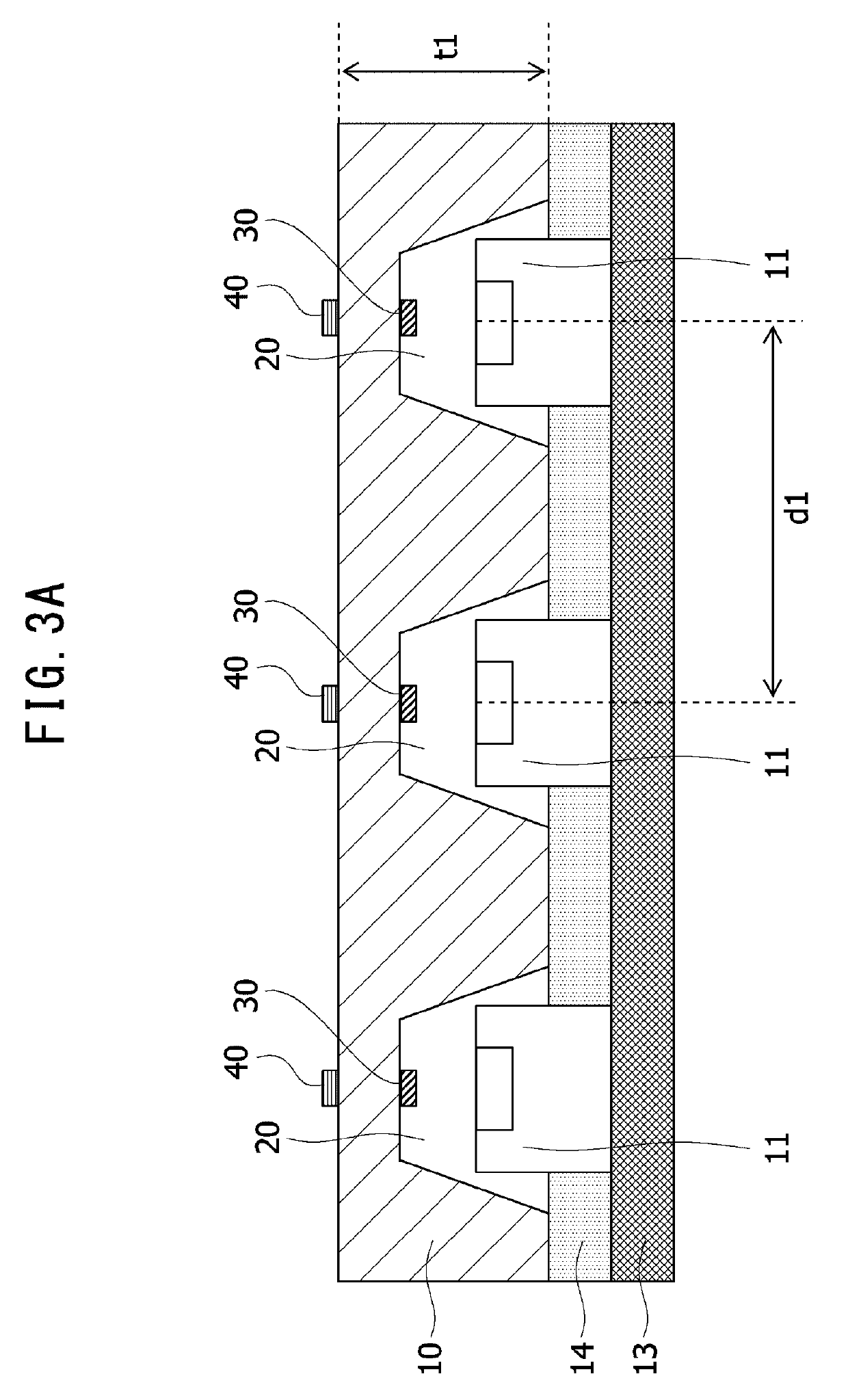
[0040]FIG. 3A is a sectional view schematically showing the light guide plate 10. The light guide plate 10 has a plurality of depressed portions 20 on the lower surface of the light guide plate 10. In other words, the depressed portions 20 are opened downward and depressed upward relative to the light guide plate 10. In addition, the plurality of light sources 11 are arranged on the mounting substrate 13, with one light source 11 being housed inside each depressed portion 20. The depressed portions 20 are also referred to as housing portions. In addition, light emitted from the light sources 11 is incident into the light guide plate 10. Due to light incident into the light guide plate 10 being refracted, reflected, and diffused inside the light guide plate 10 and emitted from a light exit surface of the light guide plate 10, the light exit surface of the light guide plate 10 is uniformly lighted. A thickness (height) t1 of the light guide plate 10 and a pitch between the light sourc...

second embodiment

[0045]FIG. 4 is a sectional view schematically showing the light guide plate 10 according to a second embodiment. A ratio of sizes of the respective components and the like are not limited to the illustrated example. In the present embodiment, components corresponding to the configuration described above will be assigned corresponding reference numerals and a description thereof will be omitted. The light guide plate 10 according to the present embodiment also includes two direction changing portions. Specifically, the first direction changing portion 30 is provided in a back end portion of the depressed portion 20 near a position on a line which passes through the light source 11 and which is perpendicular to the light exit surface. In addition, the second direction changing portion 40 is provided between the diffusing sheet 15 and the prism sheet 16 near a foot of a perpendicular dropped from the light source 11 to the diffusing sheet 15 or the prism sheet 16. To sum up the first ...

third embodiment

[0047]FIG. 5 is a sectional view schematically showing the light guide plate 10 according to a third embodiment. A ratio of sizes of the respective components and the like are not limited to the illustrated example. In the present embodiment, components corresponding to the configurations described above will be assigned corresponding reference numerals and a description thereof will be omitted.

[0048]The depressed portion 20 shown in FIG. 5 is a depression with a truncated cone shape provided on the light guide plate 10 and is configured as a through-hole. In addition, the diameter of the depressed portion 20 decreases from an opening on the lower surface side toward an opening on the upper surface side. In other words, a housing portion of the light source 11 according to the present embodiment is configured as a through-hole with a tapered side surface.

[0049]In addition, a light diffusing layer 50 formed by a diffusing material that diffuses light is provided on a side of the ligh...


PUM

PropertyMeasurementUnit
transparentaaaaaaaaaa
brightnessaaaaaaaaaa
thicknessaaaaaaaaaa

Abstract

A light guide plate includes: a depressed portion provided on an opposite side of a light exit surface from which light is emitted; a first direction changing portion which is provided inside the depressed portion and above a light emitting element in a direction oriented toward the light exit surface, the light emitting element being provided on the opposite side of the light exit surface, and which changes a direction of travel of at least a part of light of the light emitting element; and a second direction changing portion which is provided above the light emitting element and higher than the light exit surface and which changes a direction of travel of at least a part of light of the light emitting element.

Description

TECHNICAL FIELD[0001]The present invention relates to a light guide plate, a planar light source apparatus, a display apparatus, and an electronic device.BACKGROUND ART[0002]Backlight systems for liquid crystal display apparatuses include a system referred to as an edge light-type backlight and a system referred to as a direct-type backlight. Direct-type backlights which feature high light utilization efficiency and which enable higher brightness to be readily achieved are used in displays of large-size liquid crystal display apparatuses. In addition, for example, an LED (Light Emitting Diode) which emits white light is used as a light source of a backlight. In the case of a direct-type backlight, while a plurality of LEDs are arranged directly underneath a liquid crystal display apparatus, brightness non-uniformity easily occurs on the liquid crystal display apparatus between portions directly above the LEDs and other portions.[0003]Conventionally, a planar light source apparatus h...

Claims


Application Information

Patent Timeline
Patent Type & Authority Applications(United States)
IPC IPC(8): G02F1/1335F21S43/239F21V8/00
CPCG02F1/133603G02F1/133524G02F1/133611F21S43/239G02B6/0028F21S2/00F21V5/04H01L33/00G02B6/0021G02B6/0053G02F1/133606G02B6/0016G02B6/0036G02B6/0043G02F1/133607G02B3/08G02B6/0051G02B26/08G02F1/1335G02F1/133605G02F2201/305G02B6/0018G02B6/0055G02B6/0031G02B6/0025G02B6/003G02B6/0073
Inventor WATANABE, SHOTAROISHIMI, NAOKIITO, YOSHINORISHIMODA, TOMOKAZU
Owner NICHIA CORP
Why Eureka
Try Eureka