Antenna element, antenna module, and communication apparatus

Active Publication Date: 2019-07-25
MURATA MFG CO LTD
View PDF0 Cites 10 Cited by
  • Summary
  • Abstract
  • Description
  • Claims
  • Application Information

AI Technical Summary

Benefits of technology

[0026]With this configuration, the first array antenna has directivity in the first direction, the second direction, and the third direction of the communication apparatus. Further, the second array antenna has directivity in the fourth direction, the fifth direction, and the sixth direction of the communication apparatus. Thus, it is possible to provide directivity in all directions

Problems solved by technology

Therefore, an electric length and a current direction of the second radiation conductor are not fixed, and a radiation direction is directed also toward a lower elevation ang

Method used


Image

  • Antenna element, antenna module, and communication apparatus
  • Antenna element, antenna module, and communication apparatus
  • Antenna element, antenna module, and communication apparatus

Examples


first embodiment

[0045][1.1 Circuit Configuration of Communication Apparatus]

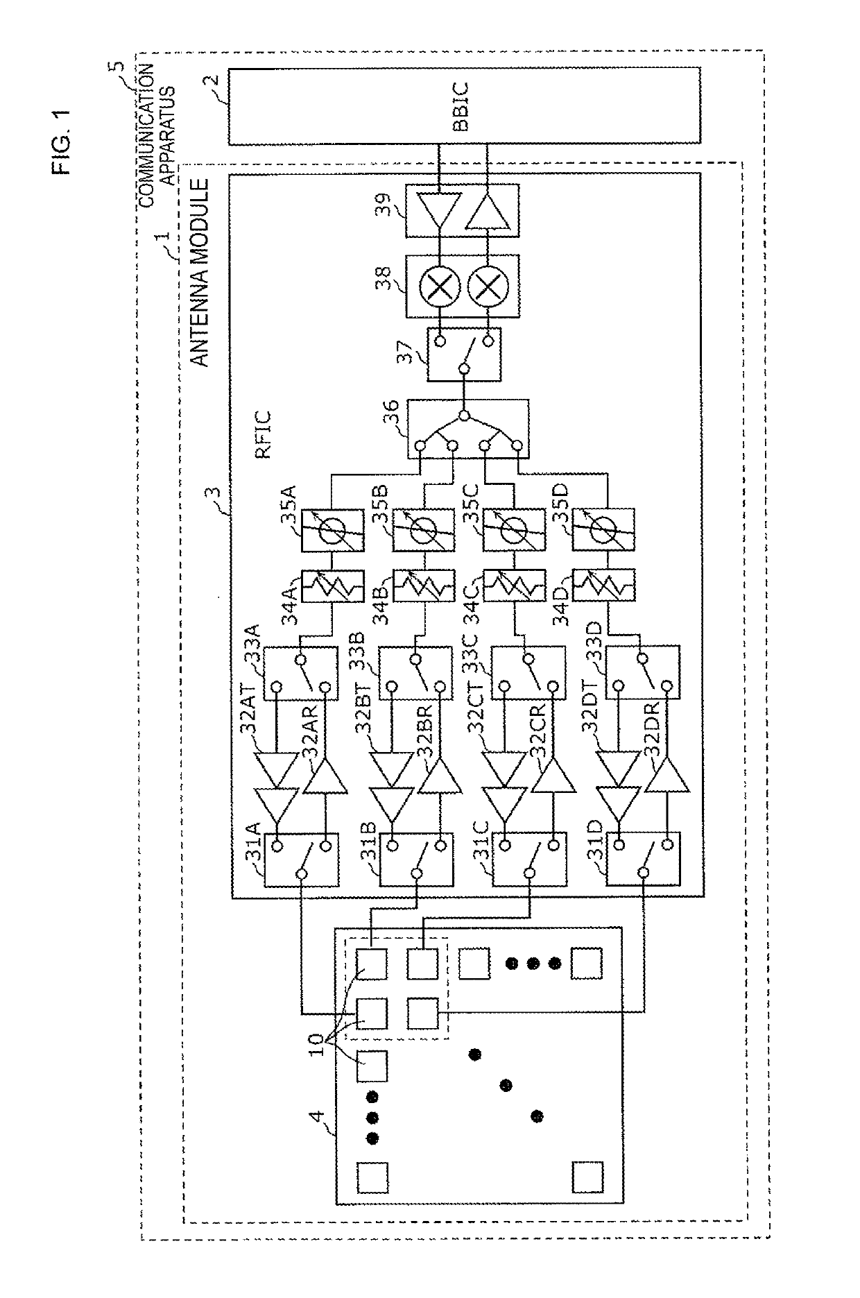
[0046]FIG. 1 is a circuit diagram of a communication apparatus 5 according to a first embodiment. The communication apparatus 5 illustrated in FIG. 1 includes an antenna module 1 and a baseband signal processing circuit (BBIC) 2. The antenna module 1 includes an array antenna 4 and an RF signal processing circuit (RFIC) 3. The communication apparatus 5 up-converts a signal transmitted from the baseband signal processing circuit (BBIC) 2 to the antenna module 1 into a radio frequency signal and radiates the signal from the array antenna 4 whereas it down-converts a radio frequency signal received by the array antenna 4 and performs signal processing on the signal in the baseband signal processing circuit (BBIC) 2.

[0047]The array antenna 4 has a plurality of patch antennas 10 arrayed in a two-dimensional manner. Each patch antenna 10 is an antenna element that operates as a radiating element radiating radio waves (high freque...

second embodiment

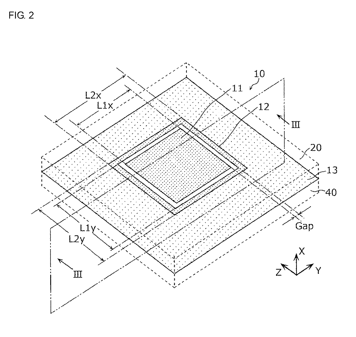
[0085]In the patch antenna 10 according to the first embodiment, the first power feeding conductor pattern 11 and the second power feeding conductor pattern 12 are arranged with only Gap interposed therebetween. A patch antenna 10A according to the embodiment has a configuration in which the first power feeding conductor pattern 11 and the second power feeding conductor pattern 12 are connected with an impedance element interposed therebetween.

[0086][2.1 Configuration of Patch Antenna]

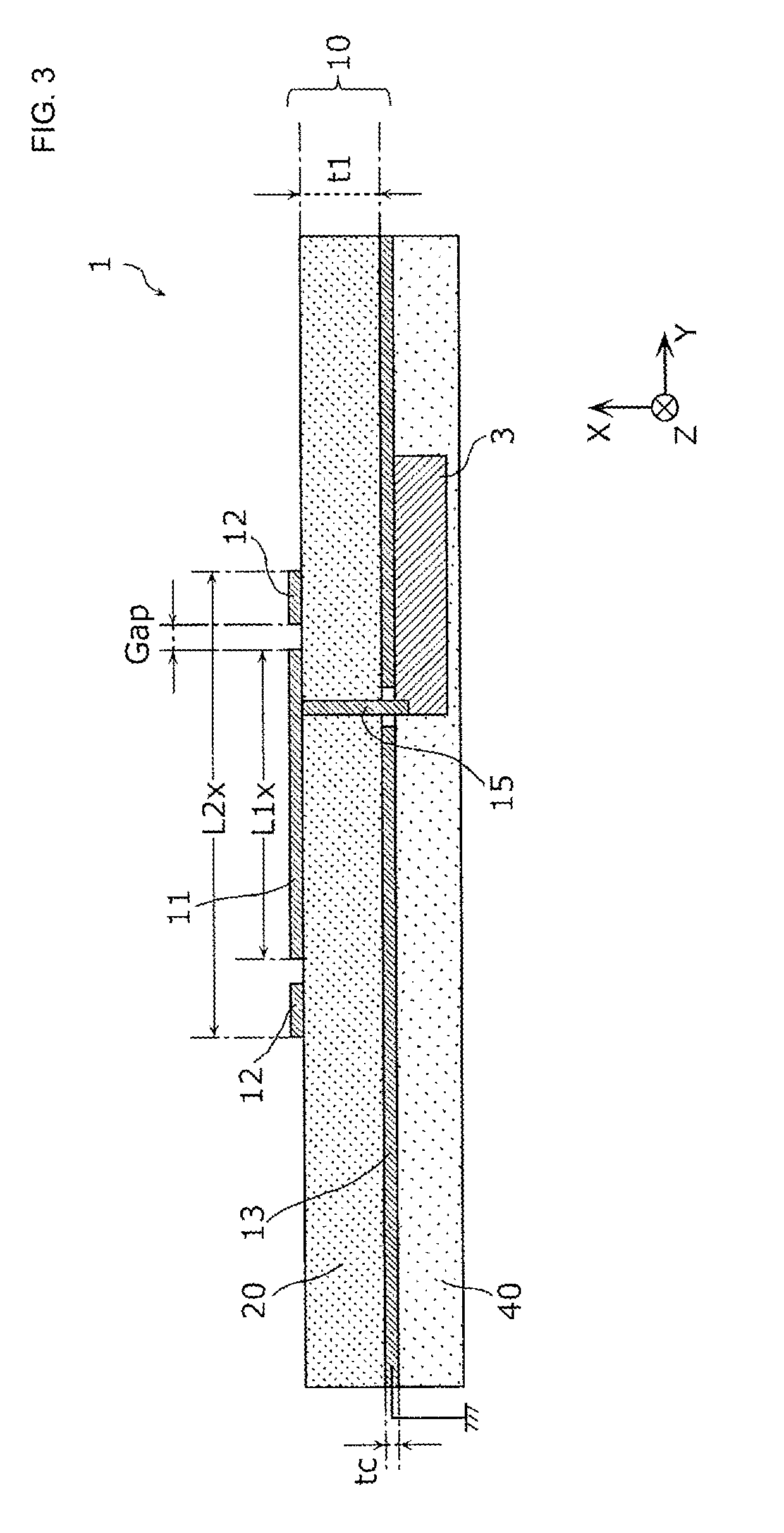
[0087]FIG. 5 is a perspective view illustrating an outer appearance of the patch antenna 10A according to a second embodiment. FIG. 6 is a cross-sectional view of an antenna module 1A according to the second embodiment. FIG. 6 is a cross-sectional view taken along a line VI-VI of FIG. 5. FIG. 5 illustrates the ground conductor pattern 13 constituting the patch antenna 10A while seeing through the dielectric substrate 20.

[0088]As illustrated in FIG. 6, the antenna module 1A includes the patch antenna 10...


PUM


Abstract

A patch antenna (10) includes a planar first power feeding conductor pattern (11) that is formed on a dielectric substrate (20) and to which a radio frequency signal is fed, a planar second power feeding conductor pattern (12) that is formed on the dielectric substrate (20) and is arranged to be isolated from the first power feeding conductor pattern (11) so as to interpose the first power feeding conductor pattern (11) in the polarization direction when the dielectric substrate (20) is seen in a plan view, and a planar ground conductor pattern (13) that is formed on the dielectric substrate (20) so as to face the first power feeding conductor pattern (11) and the second power feeding conductor pattern (12) and is set to have a ground potential, wherein the second power feeding conductor pattern (12) is not set to have the ground potential.

Description

[0001]This is a continuation of International Application No. PCT / JP2017 / 037252 filed on Oct. 13, 2017 which claims priority from Japanese Patent Application No. 2016-205559 filed on Oct. 19, 2016. The contents of these applications are incorporated herein by reference in their entireties.BACKGROUND OF THE DISCLOSUREField of the Disclosure[0002]The present disclosure relates to an antenna element, an antenna module, and a communication apparatus.Description of the Related Art[0003]Multi-band wireless communication antennas include, for example, different-frequency sharing antennas disclosed in Patent Document 1 is cited. A two-frequency sharing antenna disclosed in Patent Document 1 has a first radiation conductor formed on an upper surface of a dielectric substrate, an annular second radiation conductor formed so as to surround the first radiation conductor, and a grounding conductor formed on a lower surface of the dielectric substrate. A power feeding pin is connected to the firs...

Claims


Application Information

Patent Timeline
IPC IPC(8): H01Q9/04H01Q9/06H01Q3/36H01Q21/06H01Q1/38
CPCH01Q9/045H01Q9/0485H01Q9/06H01Q3/36H01Q21/065H01Q1/38H01Q3/26H01Q21/28H01Q5/321H01Q9/0421H01Q1/2283H01Q19/005H01Q5/364H01Q1/243H01Q25/00H01Q13/106H01Q23/00H01Q21/06H01Q13/08H01Q5/378H01Q9/04
Inventor ONAKA, KENGOYAMADA, YOSHIKI
Owner MURATA MFG CO LTD
Why Eureka
Try Eureka