LED lighting systems with triac dimmers and methods thereof

a lighting system and triac dimmer technology, applied in the field of circuits, can solve the problems of overshoot and oscillation of led current, abnormal fluctuations, and one or more leds to flicker, and achieve the effect of reducing current overshoot and oscillation and improving the compatibility of led lighting systems

Active Publication Date: 2019-07-25
ON BRIGHT ELECTRONICS SHANGHAI
View PDF4 Cites 32 Cited by
  • Summary
  • Abstract
  • Description
  • Claims
  • Application Information

AI Technical Summary

Benefits of technology

[0013]Some embodiments of the present invention provide a high-compatibility TRIAC dimmer control system for an LED lighting system and a method of using such switch control system. For example, the TRIAC dimmer control system eliminates current overshoot and oscillation caused by a sudden change of a rectified voltage during a TRIAC dimming process by controlling enablement of a constant current circuit of the system. As an example, the TRIAC dimmer control system prevents a TRIAC dimmer from operating abnormally due to current surges and thus improves the compatibility of LED lighting system with TRIAC dimmer.

Problems solved by technology

As discussed above, a resulting problem of the LED lighting system 100 is that the change in the Vbulk voltage caused by the TRIAC dimmer 190 can cause overshoot and oscillation of the LED current Iled.
For some TRIAC dimmers, this type of current overshoot and oscillation may even cause the TRIAC dimmer (e.g., the TRIAC dimmer 190) to operate abnormally (e.g., causing the TRIAC dimmer 190 to misfire), which in turn causes abnormal fluctuations in the LED current Iled and causes the one or more LEDs to flicker.

Method used


Image

  • LED lighting systems with triac dimmers and methods thereof
  • LED lighting systems with triac dimmers and methods thereof
  • LED lighting systems with triac dimmers and methods thereof

Examples


Embodiment Construction

[0026]Certain embodiments of the present invention are directed to circuits. More particularly, some embodiments of the invention provide lighting systems and methods with Triode for Alternating Current (TRIAC) dimmers. Merely by way of example, some embodiments of the invention have been applied to light emitting diodes (LEDs). But it would be recognized that the invention has a much broader range of applicability.

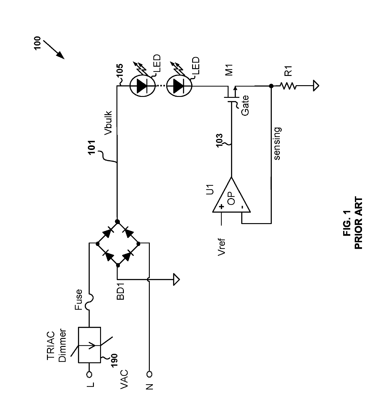
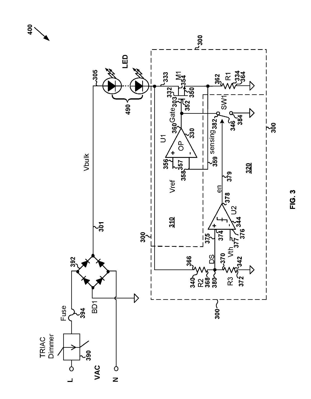
[0027]FIG. 3 is a simplified circuit diagram showing an LED lighting system with a TRIAC dimmer according to some embodiments of the present invention. This diagram is merely an example, which should not unduly limit the scope of the claims. One of ordinary skill in the art would recognize many variations, alternatives, and modifications. As shown in FIG. 3, the LED lighting system 400 includes a line (L) terminal and a neutral (N) terminal, and the system 400 also includes a TRIAC dimmer 390, a full-wave rectifying bridge 392 (e.g., a full-wave rectifying bridge BD1), a ...


PUM


Abstract

System and method for controlling one or more light emitting diodes. For example, the system for controlling one or more light emitting diodes includes a current regulation circuit coupled to a cathode of one or more light emitting diodes. The one or more light emitting diodes include the cathode and an anode configured to receive a rectified voltage. Additionally, the system includes a control circuit coupled to the cathode of the one or more light emitting diodes. The control circuit is configured to receive a first voltage from the cathode of the one or more light emitting diodes, compare a second voltage and a threshold voltage, and generate a control signal based at least in part on the second voltage and the threshold voltage. The second voltage indicates a magnitude of the first voltage.

Description

1. CROSS-REFERENCES TO RELATED APPLICATIONS[0001]This application claims priority to Chinese Patent Application No. 201711464007.9, filed Dec. 28, 2017, incorporated by reference herein for all purposes.2. BACKGROUND OF THE INVENTION[0002]Certain embodiments of the present invention are directed to circuits. More particularly, some embodiments of the invention provide lighting systems and methods with Triode for Alternating Current (TRIAC) dimmers. Merely by way of example, some embodiments of the invention have been applied to light emitting diodes (LEDs). But it would be recognized that the invention has a much broader range of applicability.[0003]As a new energy-saving and environmentally-friendly light source, light emitting diode (LED) is widely used in various fields due to its high luminance, low power consumption and long life span. For example, within a range close to a rated current, luminance of an LED often is directly proportional to the current flowing through the LED ...

Claims


Application Information

Patent Timeline
Patent Type & Authority Applications(United States)
IPC IPC(8): H05B33/08H05B44/00H05B45/59
CPCH05B33/0812H05B33/0851H05B45/00H05B45/59H05B45/31H05B45/345H05B45/10H05B45/395Y02B20/30H05B45/50
Inventor ZHU, LIQIANGZHOU, JUN
Owner ON BRIGHT ELECTRONICS SHANGHAI
Why Eureka
Try Eureka